Difference between revisions of "Orange Pi 5 detail"
(→AP6275P PCIe NIC creates WIFI hotspot via create_ap) |
(→AP6275P PCIe NIC creates WIFI hotspot via create_ap) |
||
| Line 407: | Line 407: | ||
|} | |} | ||
'''1.create_ap method to create WIFI hotspot in NAT mode'''<br><br> | '''1.create_ap method to create WIFI hotspot in NAT mode'''<br><br> | ||
| − | 1) Enter the following command to create a WIFI hotspot named orangepi and password orangepi in NAT mode<br> | + | 1) Enter the following command to create a WIFI hotspot named '''orangepi''' and password '''orangepi''' in NAT mode<br> |
{| class="wikitable" style="width:800px;" | {| class="wikitable" style="width:800px;" | ||
|- | |- | ||
| − | |orangepi@orangepi5:~$ sudo create_ap -m nat wlan0 eth0 orangepi orangepi | + | |orangepi@orangepi5:~$ '''sudo create_ap -m nat wlan0 eth0 orangepi orangepi''' |
|} | |} | ||
2) If the following information is output, it means that the WIFI hotspot is created successfully<br> | 2) If the following information is output, it means that the WIFI hotspot is created successfully<br> | ||
{| class="wikitable" style="width:800px;" | {| class="wikitable" style="width:800px;" | ||
|- | |- | ||
| − | |orangepi@orangepi5:~$ sudo create_ap -m nat wlan0 eth0 orangepi orangepi | + | |orangepi@orangepi5:~$ '''sudo create_ap -m nat wlan0 eth0 orangepi orangepi'''<br> |
| − | Config dir: /tmp/create_ap.wlan0.conf.fPItFUJ2 PID: 3831 | + | Config dir: /tmp/create_ap.wlan0.conf.fPItFUJ2 PID: 3831<br> |
| − | Network Manager found, set ap0 as unmanaged device... DONE | + | Network Manager found, set ap0 as unmanaged device... DONE <br> |
| − | Creating a virtual WiFi interface... ap0 created. | + | Creating a virtual WiFi interface... ap0 created.<br> |
| − | Sharing Internet using method: nat | + | Sharing Internet using method: nat<br> |
| − | hostapd command-line interface: hostapd_cli -p | + | hostapd command-line interface: hostapd_cli -p<br> |
/tmp/create_ap.wlan0.conf.fPItFUJ2/hostapd_ctrl ap0: interface state UNINITIALIZED->ENABLED | /tmp/create_ap.wlan0.conf.fPItFUJ2/hostapd_ctrl ap0: interface state UNINITIALIZED->ENABLED | ||
|} | |} | ||
| − | 3) Take out the mobile phone at this time, in the searched WIFI list, you can find the WIFI hotspot named orangepi created by the development board, and then click orangepi to connect to the hotspot, the password is the orangepi set above<br><br> | + | 3) Take out the mobile phone at this time, in the searched WIFI list, you can find the WIFI hotspot named '''orangepi''' created by the development board, and then click '''orangepi''' to connect to the hotspot, the password is the '''orangepi''' set above<br><br> |
[[Image:Pi-5-details-pic95.png]]<br><br> | [[Image:Pi-5-details-pic95.png]]<br><br> | ||
4) After the connection is successful, the display is as shown in the figure below<br><br> | 4) After the connection is successful, the display is as shown in the figure below<br><br> | ||
[[Image:Pi-5-details-pic96.png]]<br><br> | [[Image:Pi-5-details-pic96.png]]<br><br> | ||
| − | 5) | + | 5) In NAT mode, the wireless device connected to the hotspot of the development board requests an IP address from the DHCP service of the development board, so there will be two different network segments, for example, the IP of the development board is 192.168.1.X<br> |
{| class="wikitable" style="width:800px;" | {| class="wikitable" style="width:800px;" | ||
|- | |- | ||
| Line 438: | Line 438: | ||
RX errors 0 dropped 50 overruns 0 frame 0<br> | RX errors 0 dropped 50 overruns 0 frame 0<br> | ||
TX packets 3798 bytes 1519493 (1.5 MB)<br> | TX packets 3798 bytes 1519493 (1.5 MB)<br> | ||
| − | TX errors 0 dropped 0 overruns 0 carrier 0 collisions 0 | + | TX errors 0 dropped 0 overruns 0 carrier 0 collisions 0<br> |
| + | device interrupt 83 | ||
|} | |} | ||
| − | + | By default, the DHCP service of the development board will assign an IP address of '''192.168.12.0/24''' to the device connected to the hotspot. At this time, click on the connected WIFI hotspot '''orangepi''', and then you can see that the IP address of the mobile phone is '''192.168.12.X'''<br><br> | |
[[Image:Pi-5-details-pic97.png]]<br><br> | [[Image:Pi-5-details-pic97.png]]<br><br> | ||
[[Image:Pi-5-details-pic98.png]]<br><br> | [[Image:Pi-5-details-pic98.png]]<br><br> | ||
| − | 6) | + | 6) If you want to specify a different network segment for the connected device, you can specify it through the -g parameter, such as specifying the network segment of the access point AP through the -g parameter as 192.168.2.1<br> |
{| class="wikitable" style="width:800px;" | {| class="wikitable" style="width:800px;" | ||
|- | |- | ||
|orangepi@orangepi5:~$ '''sudo create_ap -m nat wlan0 eth0 orangepi orangepi -g 192.168.2.1''' | |orangepi@orangepi5:~$ '''sudo create_ap -m nat wlan0 eth0 orangepi orangepi -g 192.168.2.1''' | ||
|} | |} | ||
| − | + | At this time, after connecting to the hotspot through the mobile phone, click the connected WIFI hotspot orangepi, and then you can see that the IP address of the mobile phone is '''192.168.2.X'''<br><br> | |
[[Image:Pi-5-details-pic99.png]]<br><br> | [[Image:Pi-5-details-pic99.png]]<br><br> | ||
[[Image:Pi-5-details-pic100.png]]<br><br> | [[Image:Pi-5-details-pic100.png]]<br><br> | ||
| − | 7) | + | 7) If the '''--freq-band''' parameter is not specified, the hotspot created by default is in the 2.4G frequency band. If you want to create a hotspot in the 5G frequency band, you can specify it through the '''--freq-band 5''' parameter. The specific command is as follows<br> |
{| class="wikitable" style="width:800px;" | {| class="wikitable" style="width:800px;" | ||
|- | |- | ||
|orangepi@orangepi:~$ '''sudo create_ap -m nat wlan0 eth0 orangepi orangepi --freq-band 5''' | |orangepi@orangepi:~$ '''sudo create_ap -m nat wlan0 eth0 orangepi orangepi --freq-band 5''' | ||
|} | |} | ||
| − | 8) | + | 8) If you need to hide the SSID, you can specify the '''--hidden''' parameter, the specific command is as follows<br> |
{| class="wikitable" style="width:800px;" | {| class="wikitable" style="width:800px;" | ||
|- | |- | ||
|orangepi@orangepi:~$ '''sudo create_ap -m nat wlan0 eth0 orangepi orangepi --hidden''' | |orangepi@orangepi:~$ '''sudo create_ap -m nat wlan0 eth0 orangepi orangepi --hidden''' | ||
|} | |} | ||
| − | + | At this time, the mobile phone cannot search for the WIFI hotspot. You need to manually specify the name of the WIFI hotspot and enter the password to connect to the WIFI hotspot<br><br> | |
[[Image:Pi-5-details-pic101.png]]<br><br> | [[Image:Pi-5-details-pic101.png]]<br><br> | ||
| − | ''' | + | '''2.create_ap method to create WIFI hotspot in bridge mode'''<br><br> |
| − | 1) | + | 1) Enter the following command to create a WIFI hotspot named '''orangepi''' and password '''orangepi''' in bridge mode<br> |
{| class="wikitable" style="width:800px;" | {| class="wikitable" style="width:800px;" | ||
|- | |- | ||
|orangepi@orangepi:~$ '''sudo create_ap -m bridge wlan0 eth0 orangepi orangepi''' | |orangepi@orangepi:~$ '''sudo create_ap -m bridge wlan0 eth0 orangepi orangepi''' | ||
|} | |} | ||
| − | 2) | + | 2) If the following information is output, it means that the WIFI hotspot is created successfully<br> |
{| class="wikitable" style="width:800px;" | {| class="wikitable" style="width:800px;" | ||
|- | |- | ||
|orangepi@orangepi:~$ '''sudo create_ap -m bridge wlan0 eth0 orangepi orangepi'''<br> | |orangepi@orangepi:~$ '''sudo create_ap -m bridge wlan0 eth0 orangepi orangepi'''<br> | ||
[sudo] password for orangepi:<br> | [sudo] password for orangepi:<br> | ||
| − | Config dir: /tmp/create_ap.wlan0.conf.fg9U5Xgt PID: 3141<br> | + | Config dir: /tmp/create_ap.wlan0.conf.fg9U5Xgt <br> |
| − | Network Manager found, set ap0 as unmanaged device... DONE<br> | + | PID: 3141<br> |
| − | Creating a virtual WiFi interface... ap0 created. Sharing Internet using method: bridge<br> | + | Network Manager found, set ap0 as unmanaged device... DONE <br> |
| + | Creating a virtual WiFi interface... ap0 created.<br> | ||
| + | Sharing Internet using method: bridge <br> | ||
Create a bridge interface... br0 created.<br> | Create a bridge interface... br0 created.<br> | ||
hostapd command-line interface: hostapd_cli -p<br> | hostapd command-line interface: hostapd_cli -p<br> | ||
| − | /tmp/create_ap.wlan0.conf.fg9U5Xgt/hostapd_ctrl ap0: interface state UNINITIALIZED->ENABLED ap0: AP-ENABLED | + | /tmp/create_ap.wlan0.conf.fg9U5Xgt/hostapd_ctrl <br> |
| + | ap0: interface state UNINITIALIZED->ENABLED ap0: AP-ENABLED | ||
|} | |} | ||
| − | 3) | + | 3) Take out the mobile phone at this time, and you can find the WIFI hotspot named orangepi created by the development board in the searched WIFI list, and then you can click orangepi to connect to the hotspot, and the password is the orangepi set above<br><br> |
[[Image:Pi-5-details-pic102.png]]<br><br> | [[Image:Pi-5-details-pic102.png]]<br><br> | ||
| − | 4) | + | 4) After the connection is successful, the display is as shown in the figure below<br><br> |
[[Image:Pi-5-details-pic103.png]]<br><br> | [[Image:Pi-5-details-pic103.png]]<br><br> | ||
| − | 5) | + | 5) In bridge mode, the wireless device connected to the hotspot of the development board also requests an IP address from the DHCP service of the main router (the router connected to the development board), for example, the IP of the development board is '''192.168.1.X'''<br> |
{| class="wikitable" style="width:800px;" | {| class="wikitable" style="width:800px;" | ||
|- | |- | ||
|orangepi@orangepi:~$ '''ifconfig eth0'''<br> | |orangepi@orangepi:~$ '''ifconfig eth0'''<br> | ||
eth0: flags=4163<UP,BROADCAST,RUNNING,MULTICAST> mtu 1500<br> | eth0: flags=4163<UP,BROADCAST,RUNNING,MULTICAST> mtu 1500<br> | ||
| − | inet '''<span style="color:#FF0000">192.168.1.150</span>''' netmask 255.255.255.0 broadcast 192.168.1.255 <br> | + | inet '''<span style="color:#FF0000">192.168.1.150</span>''' netmask 255.255.255.0 broadcast 192.168.1.255 <br> |
| − | inet6 fe80::938f:8776:5783:afa2 prefixlen 64 scopeid 0x20<link> <br> | + | inet6 fe80::938f:8776:5783:afa2 prefixlen 64 scopeid 0x20<link><br> |
| − | ether 4a:a0:c8:25:42:82 txqueuelen 1000 (Ethernet)<br> | + | ether 4a:a0:c8:25:42:82 txqueuelen 1000 (Ethernet) <br> |
RX packets 25370 bytes 2709590 (2.7 MB)<br> | RX packets 25370 bytes 2709590 (2.7 MB)<br> | ||
RX errors 0 dropped 50 overruns 0 frame 0<br> | RX errors 0 dropped 50 overruns 0 frame 0<br> | ||
TX packets 3798 bytes 1519493 (1.5 MB)<br> | TX packets 3798 bytes 1519493 (1.5 MB)<br> | ||
| − | TX errors 0 dropped 0 overruns 0 carrier 0 collisions 0 | + | TX errors 0 dropped 0 overruns 0 carrier 0 collisions 0<br> |
| + | device interrupt 83 | ||
|} | |} | ||
| − | + | The IP of the device connected to the WIFI hotspot is also assigned by the main router, so the mobile phone connected to the WIFI hotspot and the development board are in the same network segment. At this time, click on the connected WIFI hotspot orangepi, and then you can see the IP address of the mobile phone Also 192.168.1.X<br><br> | |
[[Image:Pi-5-details-pic104.png]]<br><br> | [[Image:Pi-5-details-pic104.png]]<br><br> | ||
[[Image:Pi-5-details-pic105.png]]<br><br> | [[Image:Pi-5-details-pic105.png]]<br><br> | ||
| − | 6) | + | 6) If the --freq-band parameter is not specified, the hotspot created by default is in the 2.4G frequency band. If you want to create a hotspot in the 5G frequency band, you can specify the --freq-band 5 parameter. The specific command is as follows<br> |
{| class="wikitable" style="width:800px;" | {| class="wikitable" style="width:800px;" | ||
|- | |- | ||
|orangepi@orangepi:~$ '''sudo create_ap -m bridge wlan0 eth0 orangepi orangepi --freq-band 5''' | |orangepi@orangepi:~$ '''sudo create_ap -m bridge wlan0 eth0 orangepi orangepi --freq-band 5''' | ||
|} | |} | ||
| − | 7) | + | 7) If you need to hide the SSID, you can specify the --hidden parameter, the specific command is as follows<br> |
{| class="wikitable" style="width:800px;" | {| class="wikitable" style="width:800px;" | ||
|- | |- | ||
|orangepi@orangepi:~$ '''sudo create_ap -m bridge wlan0 eth0 orangepi orangepi --hidden''' | |orangepi@orangepi:~$ '''sudo create_ap -m bridge wlan0 eth0 orangepi orangepi --hidden''' | ||
|} | |} | ||
| − | + | At this time, the mobile phone cannot search for the WIFI hotspot. You need to manually specify the name of the WIFI hotspot and enter the password to connect to the WIFI hotspot.<br><br> | |
[[Image:Pi-5-details-pic106.png]]<br><br> | [[Image:Pi-5-details-pic106.png]]<br><br> | ||
Revision as of 11:52, 23 April 2023
Contents
- 1 How to use Win32Diskimager to burn Linux image
- 2 Linux system instructions
- 2.1 Supported Linux image types and kernel versions
- 2.2 Onboard LED Light Test Instructions
- 2.3 Ethernet port test
- 2.4 WIFI connection test
- 2.5 How to set a static IP address
- 2.6 How to use AP6275P PCIe network card
- 2.7 AP6275P PCIe NIC creates WIFI hotspot via create_ap
- 2.8 查询 HDMI 显示测试
- 2.9 查询 HDMI 转 VGA 显示测试
- 2.10 查询 HDMI 分辨率设置方法
- 2.11 蓝牙使用方法
- 2.12 查询 连接 USB 鼠标或键盘测试
- 2.13 查询 连接 USB 存储设备测试
- 2.14 查询 USB 无线网卡测试
- 2.15 查询 USB 摄像头测试
- 2.16 查询 在桌面系统中测试音频方法
- 2.17 查询 使用命令播放音频的方法
- 2.18 查询 使用命令测试录音的方法
- 2.19 26 Pin 接口引脚说明
- 3 Android 12 系统的使用说明
- 3.1 已支持的 Android 版本
- 3.2 Android 功能适配情况
- 3.3 USB 无线网卡的使用方法
- 3.4 AP6275P PCIe 网卡的使用方法
- 3.5 WIFI 的连接测试方法
- 3.6 Wi-Fi hospot 的使用方法
- 3.7 蓝牙的测试方法
- 3.8 10.1 寸 MIPI 屏幕的使用方法
- 3.9 OV13850 和 OV13855 MIPI 摄像头的测试方法
- 3.10 26pin GPIO 口测试
- 3.11 26pin 的 UART 测试
- 3.12 26pin 的 SPI 测试
- 3.13 26pin 的 PWM 测试
- 3.14 使用数据线连接 adb 调试
- 3.15 使用网络连接 adb 调试
- 3.16 Android Box 测试过的 2.4G USB 遥控器
- 3.17 Android Box 系统 HDMI CEC 功能的使用方法
How to use Win32Diskimager to burn Linux image
1) First prepare a TF card with a capacity of 16GB or more. The transmission speed of the TF card must be class 10 or above. It is recommended to use a TF card of SanDiskand other brands
2) Then use the card reader to insert the TF card into the computer
3) Then format the TF card
a. SD Card Formatter can be used to format the TF card. The download address is:
https://www.sdcard.org/downloads/formatter/eula_windows/SDCardFormatterv5_WinEN.zip
b. After downloading, unzip and install directly, and then open the software
c. If only a TF card is inserted into the computer, the drive letter of the TF card will be displayed in the "Select card" column. If multiple USB storage devices are inserted into the computer, you can select the corresponding drive letter of the TF card through the drop-down box

d. Then click "Format", a warning box will pop up before formatting, and formatting will start after selecting "Yes (Y)"

e. After formatting the TF card, the information shown in the figure below will pop up, click OK

4) Download the Linux operating system image file compression package that you want to burn from the Orange Pi data download page, and then use the decompression software to decompress it. Among the decompressed files, the file ending with ".img" is the image file of the operating system. The size is generally more than 2GB
5) Use Win32Diskimager to burn the Linux image to the TF card
a. The download page of Win32Diskimager is
http://sourceforge.net/projects/win32diskimager/files/Archive/
b. After downloading, install it directly. The interface of Win32Diskimager is as follows
a) First select the path of the image file
b) Then confirm that the drive letter of the TF card is consistent with that displayed in the "Device" column
c) Finally click "Write" to start burning
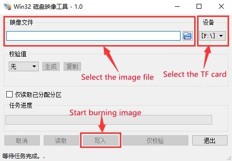
c. After the image writing is completed, click the "Exit" button to exit, and then you can pull out the TF card and insert it into the development board to start
Linux system instructions
Supported Linux image types and kernel versions
| Linux image type | kernel version | server version | desktop version |
| Debian 11 - Bullseye | Linux5.10 | support | support |
| Ubuntu 20.04 - Focal | Linux5.10 | support | support |
| Ubuntu 22.04 - Jammy | Linux5.10 | support | support |
Onboard LED Light Test Instructions
1) There are two LED lights on the development board, one is green and the other is red. The location is shown in the figure below:

2) As long as the development board is powered on, the red LED light will always be on, which is controlled by the hardware and cannot be turned off by the software.
3) The green LED light will keep flashing after the kernel is started, which is controlled by software.
4) The method of setting the green light on and off and flashing is as follows
| Note that the following operations should be performed under the root user. |
a. First enter the setting directory of the green light
| root@orangepi:~# cd /sys/class/leds/status_led |
b. The command to set the green light to stop flashing is as follows
| root@orangepi:/sys/class/leds/status_led# echo none > trigger |
c. The command to set the green light to be on is as follows
| root@orangepi:/sys/class/leds/status_led# echo 1 > brightness |
d. The command to set the green light to flash is as follows
| root@orangepi:/sys/class/leds/status_led# echo heartbeat > trigger |
Ethernet port test
1) First, insert one end of the network cable into the Ethernet interface of the development board, and connect the other end of the network cable to the router, and ensure that the network is unblocked
2) After the system starts, it will automatically assign an IP address to the Ethernet card through DHCP,No other configuration is required
3) The command to view the IP address in the Linux system of the development board is as follows
| orangepi@orangepi:~$ ip addr show eth0 2: eth0: <BROADCAST,MULTICAST,UP,LOWER_UP> mtu 1500 qdisc mq state UP group default qlen 1000 |
| When using ifconfig to view the IP address, if the following information is displayed, it is because sudo is not added. The correct command is:sudo ifconfig Command 'ifconfig' is available in the following places |
| There are three ways to check the IP address after the development board starts: 1. Connect the HDMI monitor, then log in to the system and use the ip addr show eth0 command to view the IP address In addition, it should be noted that the development board DHCP automatically assigns an IP address without any settings. |
4) The command to test the network connectivity is as follows, the ping command can be interrupted through the shortcut key of Ctrl+C
| orangepi@orangepi:~$ ping www.baidu.com -I eth0 PING www.a.shifen.com (14.215.177.38) from 192.168.1.12 eth0: 56(84) bytes of data. |
WIFI connection test
| Please do not connect to WIFI by modifying the /etc/network/interfaces configuration file. There will be problems connecting to the WIFI network in this way. |
1. The server image connects to WIFI through commands
| When the development board is not connected to Ethernet, not connected to HDMI display, but only connected to the serial port, it is recommended to use the commands demonstrated in this section to connect to the WIFI network. Because nmtui can only display characters in some serial port software (such as minicom), and cannot display the graphical interface normally. Of course, if the development board is connected to an Ethernet or HDMI display, you can also use the commands demonstrated in this section to connect to the WIFI network. |
1) First log in to the linux system, there are the following three ways
a. If the development board is connected with a network cable, you can remotely log in to the Linux system through ssh
b. If the development board is connected to the debugging serial port, you can use the serial port terminal to log in to the Linux system
c. If the development board is connected to the HDMI display, you can log in to the linux system through the terminal displayed on the HDMI
2) First use the nmcli dev wifi command to scan the surrounding WIFI hotspots
| orangepi@orangepi:~$ nmcli dev wifi |
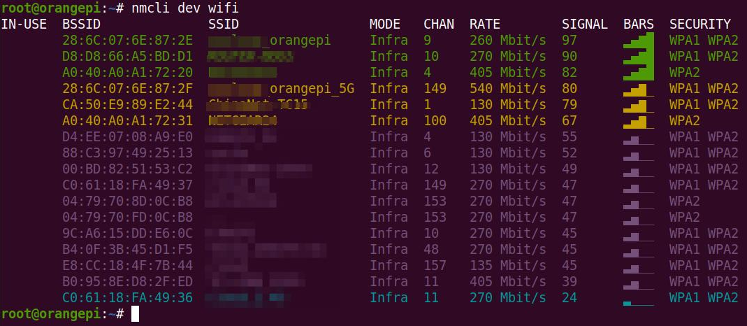
3) Then use the nmcli command to connect to the scanned WIFI hotspot, where:
a. wifi_name needs to be replaced with the name of the WIFI hotspot you want to connect to
b. wifi_passwd needs to be replaced with the password of the WIFI hotspot you want to connect to
| orangepi@orangepi:~$ nmcli dev wifi connect wifi_name password wifi_passwd
Device 'wlan0' successfully activated with 'cf937f88-ca1e-4411-bb50-61f402eef293'. |
4) You can view the IP address of wifi through the ip addr show wlan0 command
| orangepi@orangepi:~$ ip addr show wlan0 11: wlan0: <BROADCAST,MULTICAST,UP,LOWER_UP> mtu 1500 qdisc pfifo_fast state UP group default qlen 1000 |
5) Use the ping command to test the connectivity of the wifi network, and the ping command can be interrupted through the shortcut key Ctrl+C
| orangepi@orangepi:~$ ping www.orangepi.online -I wlan0 PING www.orangepi.online (182.92.236.130) from 192.168.1.49 wlan0: 56(84) bytes of data. |
2. The server image connects to WIFI in a graphical way
1) First log in to the linux system, there are the following three ways
a. If the development board is connected with a network cable, you can remotely log in to the Linux system through ssh
b. If the development board is connected to the debugging serial port, you can use the serial port terminal to log in to the linux system (please use MobaXterm for the serial port software, and minicom cannot display the graphical interface)
c. If the development board is connected to the HDMI display, you can log in to the linux system through the terminal displayed on the HDMI
2) Then enter the nmtui command in the command line to open the wifi connection interface
| orangepi@orangepi:~$ nmtui |
3) Enter the nmtui command to open the interface as shown below

4) Select Activate a connect and press Enter
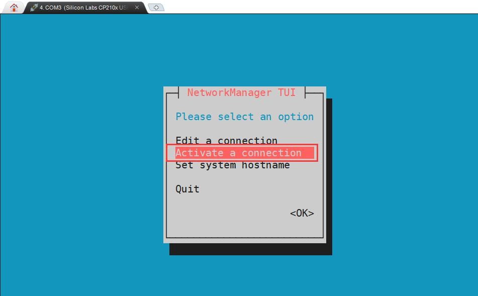
5) Then you can see all the searched WIFI hotspots

6) Select the WIFI hotspot you want to connect to, then use the Tab key to position the cursor on Activate and press Enter
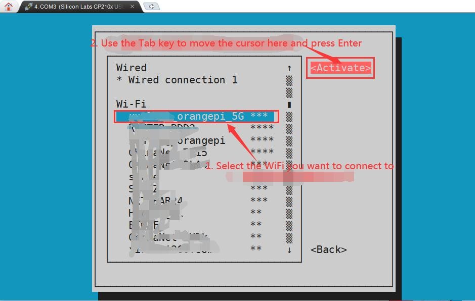
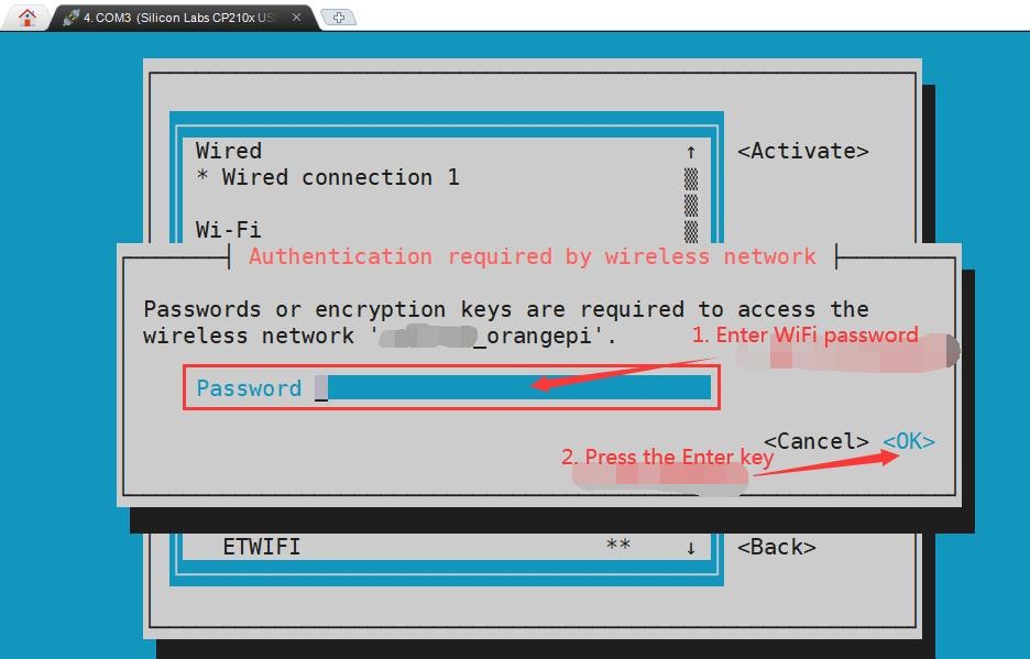
7) Then a dialog box for entering a password will pop up, enter the corresponding password in Password and press Enter to start connecting to WIFI
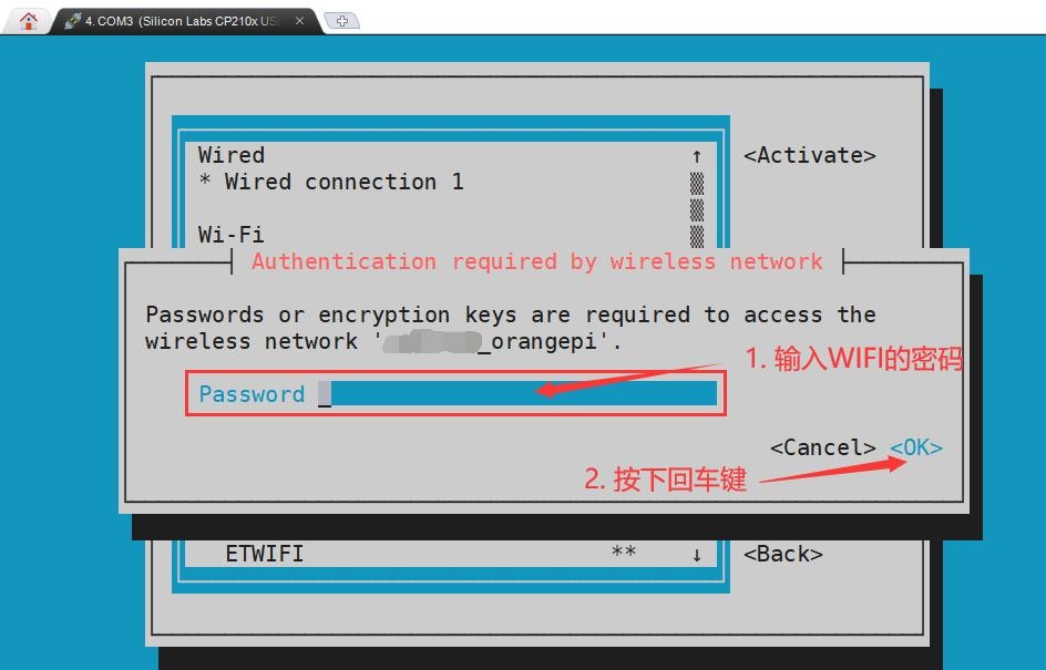
8) After the WIFI connection is successful, a "*" will be displayed in front of the connected WIFI name
9) You can view the IP address of wifi through the ip addr show wlan0 command
| orangepi@orangepi:~$ ip addr show wlan0 11: wlan0: <BROADCAST,MULTICAST,UP,LOWER_UP> mtu 1500 qdisc pfifo_fast state UP group default qlen 1000 |
10) Use the ping command to test the connectivity of the wifi network, and the ping command can be interrupted through the shortcut key Ctrl+C
| orangepi@orangepi:~$ ping www.orangepi.online -I wlan0 PING www.orangepi.online (182.92.236.130) from 192.168.1.49 wlan0: 56(84) bytes of data. |
3. Test method of desktop image
1) Click the network configuration icon in the upper right corner of the desktop (please do not connect the network cable when testing WIFI)

2) Click More networks in the pop-up drop-down box to see all scanned WIFI hotspots, and then select the WIFI hotspot you want to connect to

3) Then enter the password of the WIFI hotspot, and then click Connect to start connecting to WIFI
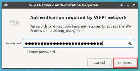
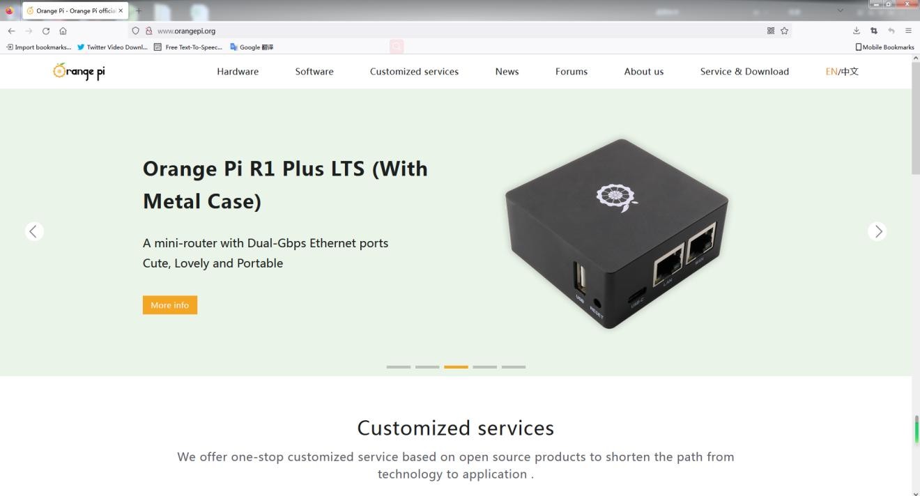
4) After connecting to WIFI, you can open the browser to check whether you can access the Internet. The entrance of the browser is shown in the figure below

5) If you can open other web pages after opening the browser, it means that the WIFI connection is normal
How to set a static IP address
1.Use the nmtui command to set a static IP address
1) First run the nmtui command
| orangepi@orangepi:~$ nmtui |
2) Then select Edit a connection and press Enter

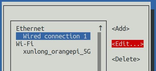
3) Then select the network interface that needs to set a static IP address, for example, to set the static IP address of the Ethernet interface, select Wired connection 1

4) Then select Edit via the Tab key and press the Enter key
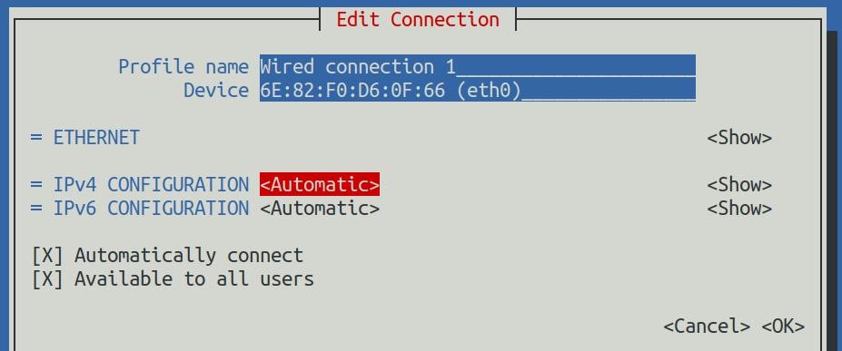
5) Then use the Tab key to move the cursor to the <Automatic> position shown in the figure below to configure IPv4
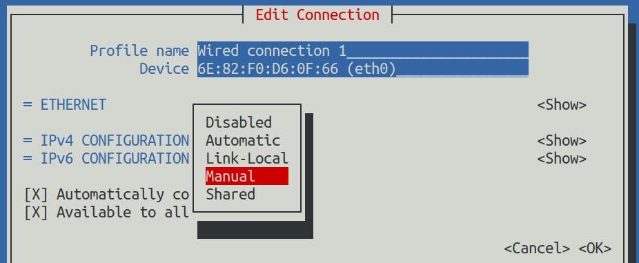
6) Then press Enter, select Manual through the up and down arrow keys, and press Enter to confirm
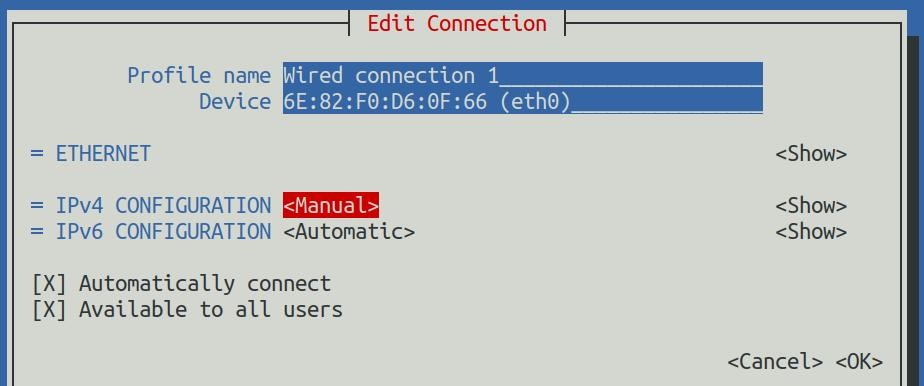
7) The display after selection is shown in the figure below
8) Then move the cursor to <Show> via the Tab key
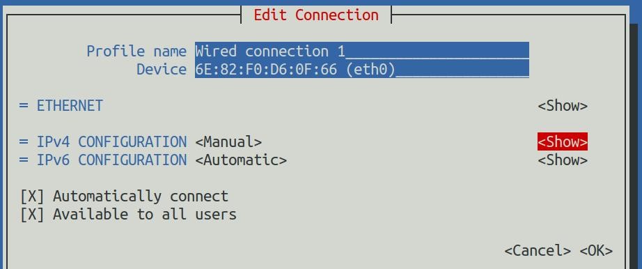
9) Then press Enter, and the following setting interface will pop up after entering
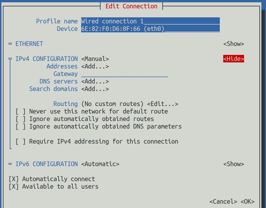
10) Then you can set the IP address (Addresses), gateway (Gateway) and DNS server address in the position shown in the figure below (there are many other setting options in it, please explore by yourself),Please set it according to your specific needs, the value set in the figure below is just an example
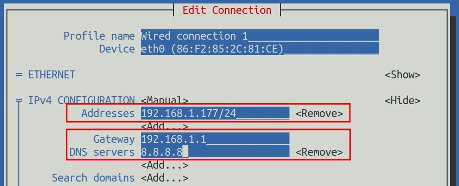
11) After setting, move the cursor to <OK> in the lower right corner, and press Enter to confirm

12) Then click <Back> to return to the previous selection interface
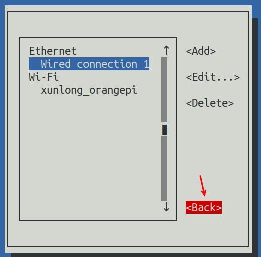
13) Then select Activate a connection, then move the cursor to <OK>, and finally click Enter
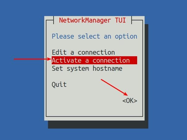
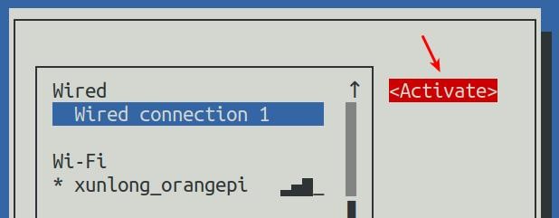
14) Then select the network interface that needs to be set, such as Wired connection 1, then move the cursor to <Deactivate>, and press Enter to disable Wired connection 1

15) Then please do not move the cursor, and then press the Enter key to re-enable Wired connection 1, so that the static IP address set earlier will take effect
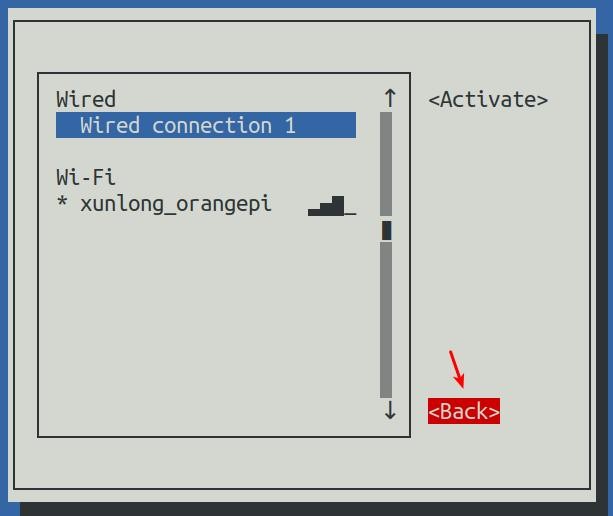
16) Then you can exit nmtui through the <Back> and Quit buttons
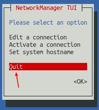
17) Then through ip addr show eth0, you can see that the IP address of the network port has changed to the static IP address set earlier
| orangepi@orangepi:~$ ip addr show eth0 3: eth0: <BROADCAST,MULTICAST,UP,LOWER_UP> mtu 1500 qdisc pfifo_fast state UP group default qlen 1000 |
18) Then you can test the connectivity of the network to check whether the IP address is configured OK, and the ping command can be interrupted through the shortcut key Ctrl+C
| orangepi@orangepi:~$ ping 192.168.1.47 -I eth0 PING 192.168.1.47 (192.168.1.47) from 192.168.1.188 eth0: 56(84) bytes of data. |
2.Use the nmcli command to set a static IP address
1) If you want to set the static IP address of the network port, please insert the network cable into the development board first. If you need to set the static IP address of WIFI, please connect the WIFI first, and then start to set the static IP address
2) Then you can view the name of the network device through the nmcli con show command, as shown below
a. orangepi is the name of the WIFI network interface (the name is not necessarily the same)
b. Wired connection 1 is the name of the Ethernet interface
| orangepi@orangepi:~$ nmcli con show |
| NAME | UUID | TYPE | DEVICE |
| orangepi | cfc4f922-ae48-46f1-84e1-2f19e9ec5e2a | wifi | wlan0 |
| Wired connection 1 | 9db058b7-7701-37b8-9411-efc2ae8bfa30 | ethernet | eth0 |
3) Then enter the following command, where
a. "Wired connection 1" means to set the static IP address of the Ethernet port. If you need to set the static IP address of the WIFI, please modify it to the corresponding name of the WIFI network interface (you can get it through the nmcli con show command)
b. ipv4.addresses is followed by the static IP address to be set, which can be modified to the value you want to set
c. ipv4.gateway represents the address of the gateway
| orangepi@orangepi:~$ nmcli con mod "Wired connection 1" \ ipv4.addresses "192.168.1.110" \ |
4) Then restart the linux system
| orangepi@orangepi:~$ sudo reboot |
5) Then re-enter the linux system and use the ip addr show eth0 command to see that the IP address has been set to the desired value
| orangepi@orangepi:~$ ip addr show eth0 3: eth0: <BROADCAST,MULTICAST,UP,LOWER_UP> mtu 1500 qdisc pfifo_fast state UP group default qlen 1000 |
How to use AP6275P PCIe network card
1) First, you need to purchase an AP6275P PCIe network card as shown in the figure below

2) Then insert the AP6275P PCIe network card into the M.2 interface of the development board and fix it
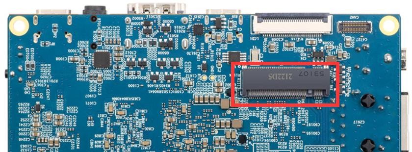
3) Then open the configuration of the AP6275P PCIe network card in the linux system, the steps are as follows:
a. First run orangepi-config, normal users remember to add sudo permission
| orangepi@orangepi:~$ sudo orangepi-config |
b. Then select System
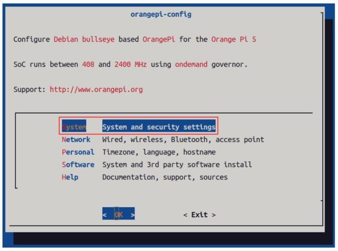
c. Then select Hardware
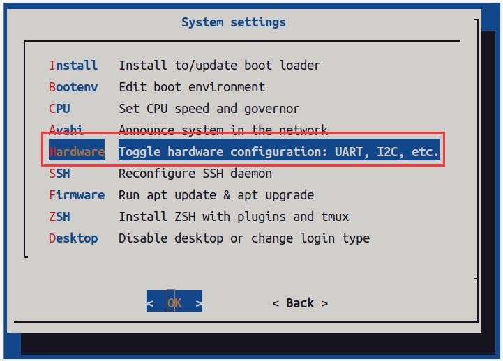
d. Then use the arrow keys on the keyboard to navigate to wifi-ap6275p, and then use the space to select
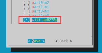
e. Then select <Save> to save

f. Then select <Back>

g. Then select <Reboot> to restart the system to make the configuration take effect

| The above settings will eventually add the configuration of overlays=wifi-ap6275p to /boot/orangepiEnv.txt. After setting, you can check it first. If this configuration does not exist, then there is a problem with the settings. If you find it troublesome to use orangepi-config, you can also open /boot/orangepiEnv.txt, and then add the configuration of overlays=wifi-ap6275p. |
4) If everything is normal after restarting the system, use the following command to see the device nodes of WIFI and Bluetooth
a. The command to view the WIFI device node is as follows:
| orangepi@orangepi:~$ ip addr show wlan0 3: wlan0: <NO-CARRIER,BROADCAST,MULTICAST,UP,LOWER_UP> mtu 1500 |
b. The command to view the Bluetooth device node is as follows:
| orangepi@orangepi:~$ hciconfig -a hci0: Type: Primary Bus: UART |
5) For the wifi connection and test method, please refer to the section of WIFI connection test, which will not be repeated here
6) For the test method of Bluetooth, please refer to the section on Bluetooth usage, so I won’t go into details here
AP6275P PCIe NIC creates WIFI hotspot via create_ap
| create_ap is a script that helps quickly create WIFI hotspots on Linux, and supports bridge and NAT modes. It can automatically combine hostapd, dnsmasq and iptables to complete the setting of WIFI hotspots, avoiding complex configuration for users. The github address is as follows: |
| If you using the latest image, the create_ap script has been pre-installed, and you can create a WIFI hotspot through the create_ap command. The basic command format of create_ap is as follows: create_ap [options] <wifi-interface> [<interface-with-internet>] |
1.create_ap method to create WIFI hotspot in NAT mode
1) Enter the following command to create a WIFI hotspot named orangepi and password orangepi in NAT mode
| orangepi@orangepi5:~$ sudo create_ap -m nat wlan0 eth0 orangepi orangepi |
2) If the following information is output, it means that the WIFI hotspot is created successfully
| orangepi@orangepi5:~$ sudo create_ap -m nat wlan0 eth0 orangepi orangepi Config dir: /tmp/create_ap.wlan0.conf.fPItFUJ2 PID: 3831 |
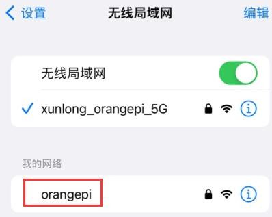
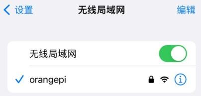
3) Take out the mobile phone at this time, in the searched WIFI list, you can find the WIFI hotspot named orangepi created by the development board, and then click orangepi to connect to the hotspot, the password is the orangepi set above
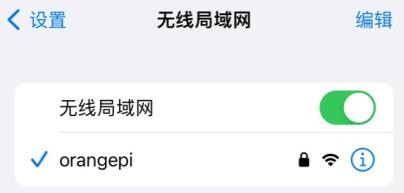
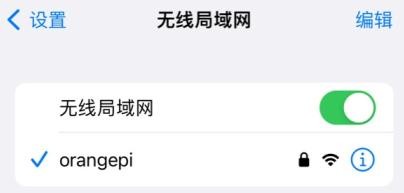
4) After the connection is successful, the display is as shown in the figure below
5) In NAT mode, the wireless device connected to the hotspot of the development board requests an IP address from the DHCP service of the development board, so there will be two different network segments, for example, the IP of the development board is 192.168.1.X
| orangepi@orangepi5:~$ ifconfig eth0 eth0: flags=4163<UP,BROADCAST,RUNNING,MULTICAST> mtu 1500 |
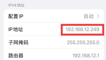
By default, the DHCP service of the development board will assign an IP address of 192.168.12.0/24 to the device connected to the hotspot. At this time, click on the connected WIFI hotspot orangepi, and then you can see that the IP address of the mobile phone is 192.168.12.X
6) If you want to specify a different network segment for the connected device, you can specify it through the -g parameter, such as specifying the network segment of the access point AP through the -g parameter as 192.168.2.1
| orangepi@orangepi5:~$ sudo create_ap -m nat wlan0 eth0 orangepi orangepi -g 192.168.2.1 |
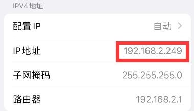
At this time, after connecting to the hotspot through the mobile phone, click the connected WIFI hotspot orangepi, and then you can see that the IP address of the mobile phone is 192.168.2.X
7) If the --freq-band parameter is not specified, the hotspot created by default is in the 2.4G frequency band. If you want to create a hotspot in the 5G frequency band, you can specify it through the --freq-band 5 parameter. The specific command is as follows
| orangepi@orangepi:~$ sudo create_ap -m nat wlan0 eth0 orangepi orangepi --freq-band 5 |
8) If you need to hide the SSID, you can specify the --hidden parameter, the specific command is as follows
| orangepi@orangepi:~$ sudo create_ap -m nat wlan0 eth0 orangepi orangepi --hidden |
At this time, the mobile phone cannot search for the WIFI hotspot. You need to manually specify the name of the WIFI hotspot and enter the password to connect to the WIFI hotspot

2.create_ap method to create WIFI hotspot in bridge mode
1) Enter the following command to create a WIFI hotspot named orangepi and password orangepi in bridge mode
| orangepi@orangepi:~$ sudo create_ap -m bridge wlan0 eth0 orangepi orangepi |
2) If the following information is output, it means that the WIFI hotspot is created successfully
| orangepi@orangepi:~$ sudo create_ap -m bridge wlan0 eth0 orangepi orangepi [sudo] password for orangepi: |
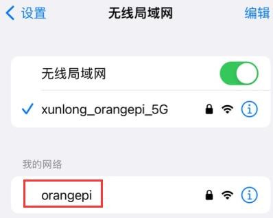
3) Take out the mobile phone at this time, and you can find the WIFI hotspot named orangepi created by the development board in the searched WIFI list, and then you can click orangepi to connect to the hotspot, and the password is the orangepi set above
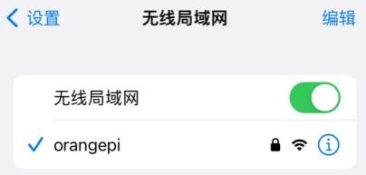
4) After the connection is successful, the display is as shown in the figure below
5) In bridge mode, the wireless device connected to the hotspot of the development board also requests an IP address from the DHCP service of the main router (the router connected to the development board), for example, the IP of the development board is 192.168.1.X
| orangepi@orangepi:~$ ifconfig eth0 eth0: flags=4163<UP,BROADCAST,RUNNING,MULTICAST> mtu 1500 |
The IP of the device connected to the WIFI hotspot is also assigned by the main router, so the mobile phone connected to the WIFI hotspot and the development board are in the same network segment. At this time, click on the connected WIFI hotspot orangepi, and then you can see the IP address of the mobile phone Also 192.168.1.X
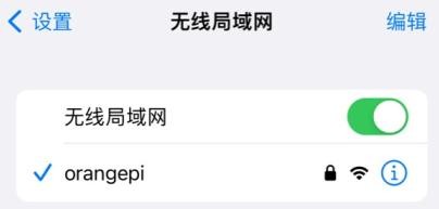
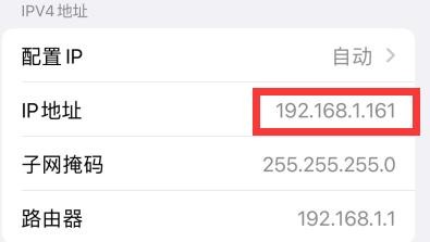
6) If the --freq-band parameter is not specified, the hotspot created by default is in the 2.4G frequency band. If you want to create a hotspot in the 5G frequency band, you can specify the --freq-band 5 parameter. The specific command is as follows
| orangepi@orangepi:~$ sudo create_ap -m bridge wlan0 eth0 orangepi orangepi --freq-band 5 |
7) If you need to hide the SSID, you can specify the --hidden parameter, the specific command is as follows
| orangepi@orangepi:~$ sudo create_ap -m bridge wlan0 eth0 orangepi orangepi --hidden |
At this time, the mobile phone cannot search for the WIFI hotspot. You need to manually specify the name of the WIFI hotspot and enter the password to connect to the WIFI hotspot.

查询 HDMI 显示测试
1) 使用 HDMI 转 HDMI 线连接 Orange Pi 开发板和 HDMI 显示器

2) 启动 linux 系统后如果 HDMI 显示器有图像输出说明 HDMI 接口使用正常
| 注意,很多笔记本电脑虽然带有 HDMI 接口,但是笔记本的 HDMI 接口一般只有输出功能,并没有 HDMI in 的功能,也就是说并不能将其他设备的 HDMI 输出显示到笔记本的屏幕上。 当想把开发板的 HDMI 接到笔记本电脑 HDMI 接口时,请先确认清楚您的笔记本是支持 HDMI in 的功能。 |
| 当 HDMI 没有显示的时候,请先检查下 HDMI 线有没有插紧,确认接线没问题后,可以换一个不同的屏幕试下有没有显示。 |
查询 HDMI 转 VGA 显示测试
1) 首先需要准备下面的配件
a. HDMI 转 VGA 转换器

b. 一根 VGA 线

c. 一个支持 VGA 接口的显示器或者电视
2) HDMI 转 VGA 显示测试如下所示
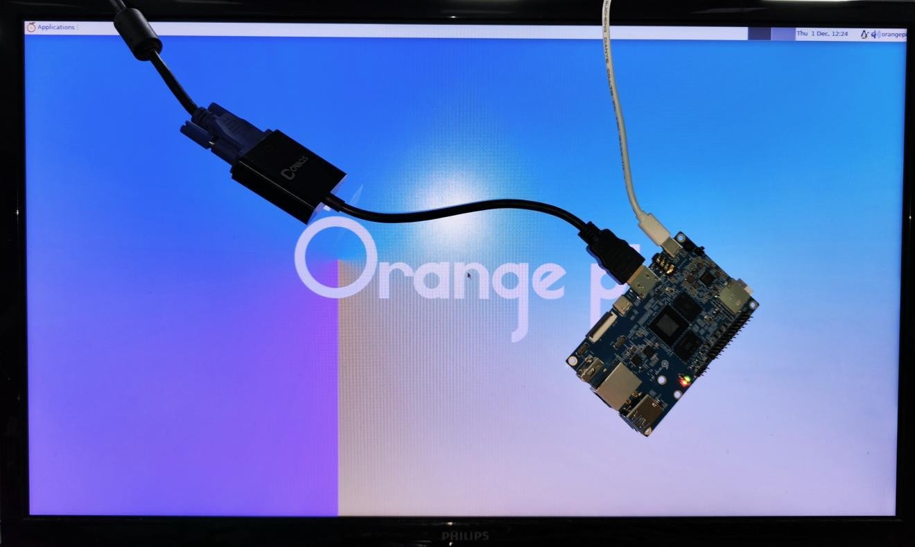
| 使用 HDMI 转 VGA 显示时,开发板以及开发板的 Linux 系统是不需要做任何设置的,只需要开发板 HDMI 接口能正常显示就可以了。所以如果测试有问题,请检查 HDMI 转 VGA 转换器、VGA 线以及显示器是否有问题。 |
查询 HDMI 分辨率设置方法
1) 首先在 Settings 中打开 Display

2) 然后就能看到系统当前的分辨率
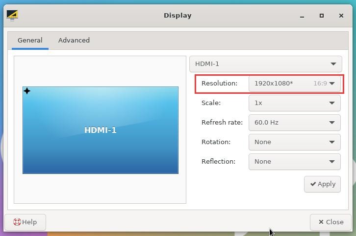
3) 点击 Resolution(分辨率)的下拉框,就可以看到显示器当前支持的所有分辨率
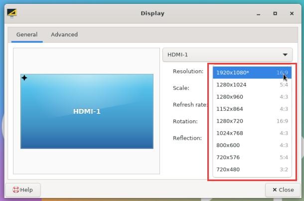
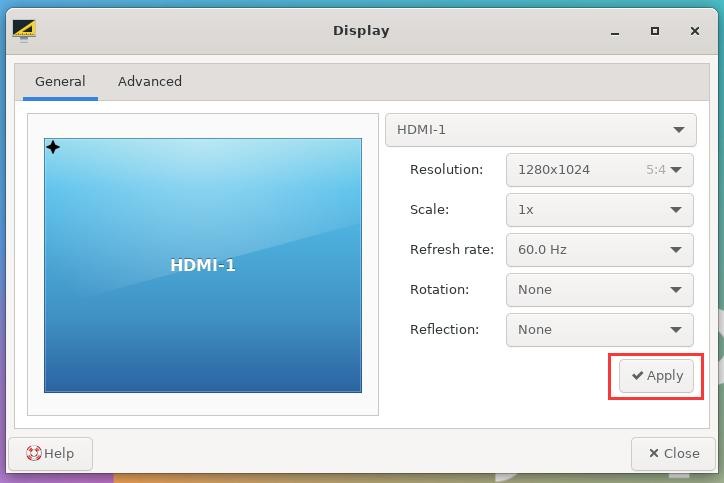
4) 然后选择想要设置的分辨率,再点击 Apply
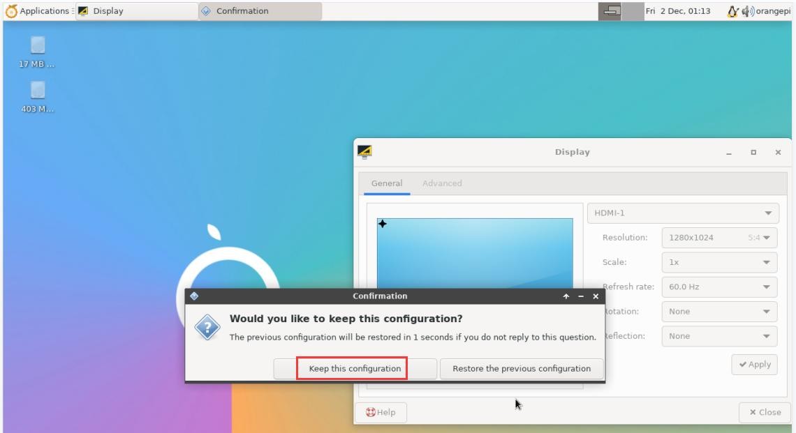
5) 等新的分辨率设置完后再选择 Keep the configuration 即可
蓝牙使用方法
| 请注意,Orange Pi 5 开发板上是没有蓝牙模块的,需要外接带蓝牙的 PCIe 网卡或者带蓝牙的 USB 网卡才能使用蓝牙功能。 外接 PCIe 网卡的使用说明请参考 AP6275P PCIe 网卡的使用方法一小节。外接 USB 网卡的使用说明请参考 USB 无线网卡测试一小节。 |
桌面版镜像的测试方法
1) 点击桌面右上角的蓝牙图标

2) 然后选择适配器

3) 如果有提示下面的界面,请选择 Yes

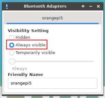
4) 然后在蓝牙的适配器设置界面中设置 Visibility Setting 为 Always visible,然后关闭即可
5) 然后打开蓝牙设备的配置界面

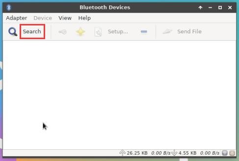
6) 点击 Search 即可开始扫描周围的蓝牙设备
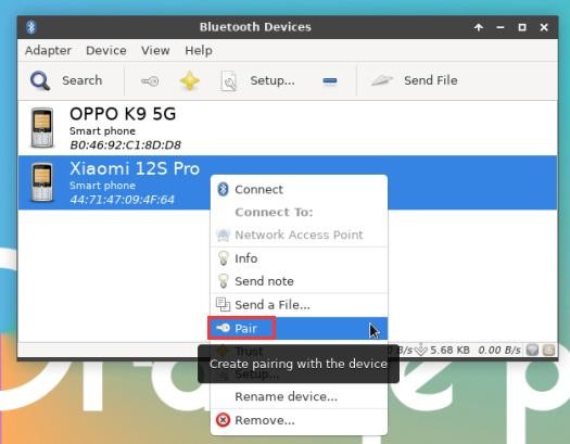
7) 然后选择想要连接的蓝牙设备,再点击鼠标右键就会弹出对此蓝牙设备的操作界面,选择 Pair 即可开始配对,这里演示的是和 Android 手机配对
8) 配对时,桌面的右上角会弹出配对确认框,选择 Confirm 确认即可,此时手机上也同样需要进行确认

9) 和手机配对完后,可以选择已配对的蓝牙设备,然后右键选择 Send a File 即可开始给手机发送一张图片
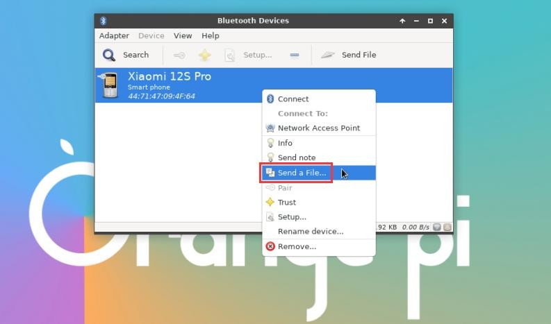
10) 发送图片的界面如下所示

查询 连接 USB 鼠标或键盘测试
1) 将 USB 接口的键盘插入 Orange Pi 开发板的 USB 接口中
2) 连接 Orange Pi 开发板到 HDMI 显示器
3) 如果鼠标或键盘能正常操作系统说明 USB 接口使用正常(鼠标只有在桌面版的系统中才能使用)
查询 连接 USB 存储设备测试
1) 首先将 U 盘或者 USB 移动硬盘插入 Orange Pi 开发板的 USB 接口中
2) 执行下面的命令如果能看到 sdX 的输出说明 U 盘识别成功
|
orangepi@orangepi:~$ cat /proc/partitions | grep "sd" |
3) 使用 mount 命令可以将 U 盘挂载到/mnt 中,然后就能查看 U 盘中的文件了
| orangepi@orangepi:~$ sudo mount /dev/sda1 /mnt/ orangepi@orangepi:~$ ls /mnt/ |
4) 挂载完后通过 df -h 命令就能查看 U 盘的容量使用情况和挂载点
|
orangepi@orangepi:~$ df -h | grep "sd" |
查询 USB 无线网卡测试
目前测试过的能用的 USB 无线网卡如下所示,其他型号的 USB 无线网卡请自行测试,如果无法使用就需要移植对应的 USB 无线网卡驱动
| 序号 | 型号 | |
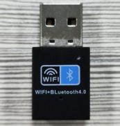
| 1 | RTL8723BU 支持 2.4G WIFI+BT4.0 |
|
| 2 | RTL8811 支持 2.4G +5G WIFI |

|
| 3 | RTL8821CU 支持 2.4G +5G WIFI 支持 BT 4.2 |

|
1、RTL8723BU 测试
1) 首先将 RTL8723BU 无线网卡模块插入开发板的 USB 接口中
2) 然后linux 系统会自动加载RTL8723BU 蓝牙和WIFI 相关的内核模块,通过 lsmod命令可以看到下面内核模块已自动加载
orangepi@orangepi:~$ lsmod
|
3) 通过 dmesg 命令可以看到 RTL8723BU 模块的加载信息
| orangepi@orangepi:~$ dmesg |
4) 然后通过 sudo ifconfig 命令可以看到 RTL8723BU WIFI 的设备节点,WIFI 的连接和测试方法请参看 WIFI 连接测试一节,这里不再赘述
| orangepi@orangepi:~$ sudo ifconfig wlx0013eff458ae wlx0013eff458ae: flags=4099<UP,BROADCAST,MULTICAST> mtu 1500 |
5) 然后通过 hciconfig 命令可以看到 USB 的蓝牙设备
| orangepi@orangepi:~$ sudo apt update && sudo apt install bluez orangepi@orangepi:~$ hciconfig |
6) 在桌面中也可以看到出现了蓝牙图标,此时蓝牙还未打开,所以会显示一个红色的 x

7) 点击 Turn Bluetooth On 可以打开蓝牙

8) 打开蓝牙后的显示如下所示

9) 蓝牙的测试方法请参看 蓝牙使用方法一节,这里不再赘述
2、RTL8811 测试
1) 首先将 RTL8811 无线网卡模块插入开发板的 USB 接口中
2) 然后 linux 系统会自动加载 RTL8811 WIFI 相关的内核模块,通过 lsmod 命令可以看到下面内核模块已自动加载
orangepi@orangepi:~$ lsmod
|
3) 通过 dmesg 命令可以看到 RTL8811 模块的加载信息
| orangepi@orangepi:~$ dmesg [ 118.618194] usb 2-1: new high-speed USB device number 2 using ehci-platform |
4) 然后通过 sudo ifconfig 命令可以看到 WIFI 的设备节点,WIFI 的连接和测试方法请参看 WIFI 连接测试一节,这里不再赘述
| orangepi@orangepi:~$ sudo ifconfig wlx1cbfced9d260 wlx1cbfced9d260: flags=4099<UP,BROADCAST,MULTICAST> mtu 1500 |
3、RTL8821CU 测试
1) 首先将 rtl8821cu 无线网卡模块插入开发板的 usb 接口中
2) 然后使用 lsusb 命令就可以看到 rtl8821cu usb wifi 模块的设备信息,请确保 USB模块没有处于 Driver CDROM Mode
| grep "Realtek" Bus 002 Device 003: ID 0bda:c820 Realtek Semiconductor Corp. 802.11ac NIC |
| grep "Realtek" Bus 002 Device 002: ID 0bda:1a2b Realtek Semiconductor Corp. RTL8188GU 802.11n WLAN Adapter (Driver CDROM Mode) 如果 lsusb 命令看到的 USB WIFI 模块处于 Driver CDROM Mode,请重新拔插下 USB WIFI 模块。如果还不行,请手动执行下面的命令切换下模式: |
3) linux 系统会自动加载 rtl8821cu 蓝牙和 wifi 相关的内核模块,通过 lsmod 命令可以看到下面内核模块已自动加载
orangepi@orangepi:~$ lsmod
|
4) 通过 dmesg 命令可以看到 rtl8821cu 模块的加载信息
| orangepi@orangepi:~$ dmesg ...... |
5) 然后通过 sudo ifconfig 命令可以看到 rtl8821cu wifi 的设备节点,wifi 的连接和测试方法请参看 WIFI 连接测试一节,这里不再赘述
| orangepi@orangepi:~$ sudo ifconfig wlx90de80521825 wlx90de80521825: flags=4099<UP,BROADCAST,MULTICAST> mtu 1500 |
6) 然后通过 hciconfig 命令可以看到 USB 的蓝牙设备
| orangepi@orangepi:~$ sudo apt-get update && sudo apt-get install -y bluez orangepi@orangepi:~$ hciconfig |
7) 在桌面中也可以看到出现了蓝牙图标,此时蓝牙还未打开,所以会显示一个红色的 x

8) 点击 Turn Bluetooth On 可以打开蓝牙

9) 打开蓝牙后的显示如下所示

蓝牙的测试方法请参看 蓝牙使用方法一节,这里不再赘述
查询 USB 摄像头测试
1) 首先需要准备一个下图所示的或者类似的支持 UVC 协议的 USB 摄像头,然后将USB 摄像头插入到 Orange Pi 开发板的 USB 接口中

2) 通过 v4l2-ctl 命令可以看到 USB 摄像头的设备节点信息为/dev/video0
| orangepi@orangepi:~$ v4l2-ctl --list-devices Q8 HD Webcam: Q8 HD Webcam (usb-fc880000.usb-1): |
| 注意 v4l2 中的 l 是小写字母 l,不是数字 1。 另外 video 的序号不一定都是 video0,请以实际看到的为准。 |
3) 在桌面系统中可以使用 Cheese 直接打开 USB 摄像头,Cheese 打开方法如下图所示:
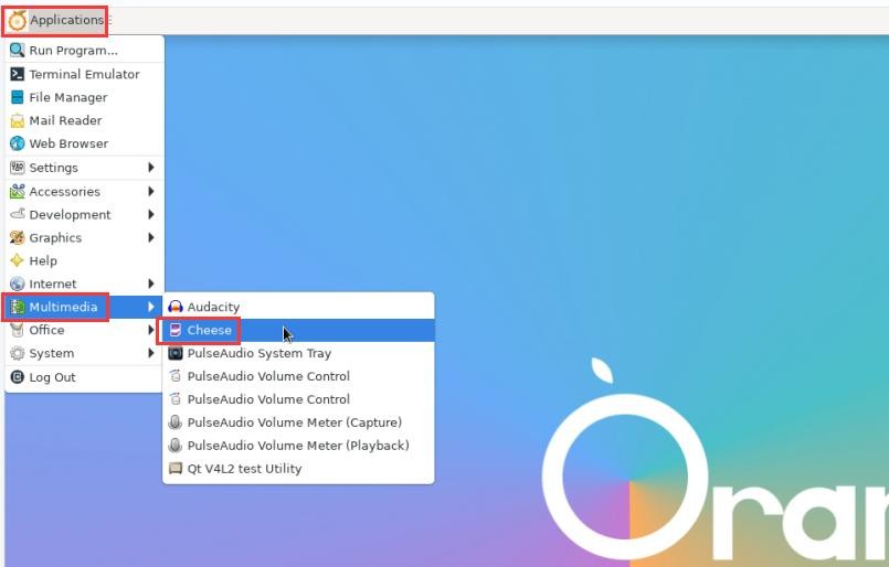
Cheese 打开 USB 摄像头后的界面如下图所示:

4) 使用 fswebcam 测试 USB 摄像头的方法
a. 安装 fswebcam
| orangepi@orangepi:~$ sudo apt update orangepi@orangepi:~$ sudo apt-get install -y fswebcam |
b. 安装完 fswebcam 后可以使用下面的命令来拍照
a) -d 选项用于指定 USB 摄像头的设备节点
b) --no-banner 用于去除照片的水印
c) -r 选项用于指定照片的分辨率
d) -S 选项用设置于跳过前面的帧数
e) ./image.jpg 用于设置生成的照片的名字和路径
| orangepi@orangepi:~$ sudo fswebcam -d /dev/video0 \ --no-banner -r 1280x720 -S 5 ./image.jpg |
c. 在服务器版的 linux 系统中,拍完照后可以使用 scp 命令将拍好的图片传到Ubuntu PC 上镜像观看
| orangepi@orangepi:~$ scp image.jpg [email protected]:/home/test(根据实际情况修改 IP 地址和路径) |
d. 在桌面版的 linux 系统中,可以通过 HDMI 显示器直接查看拍摄的图片
查询 在桌面系统中测试音频方法
1) 首先打开文件管理器

2) 然后找到下面这个文件(如果系统中没有这个音频文件,可以自己上传一个音频文件到系统中)
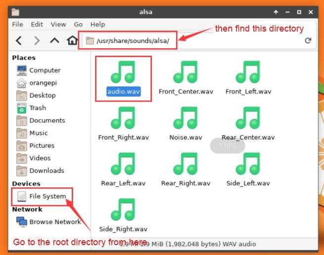
3) 然后选中 audio.wav 文件,右键选择使用 vlc 打开就可以开始播放

4) 换 HDMI 播放和耳机播放等不同音频设备的方法
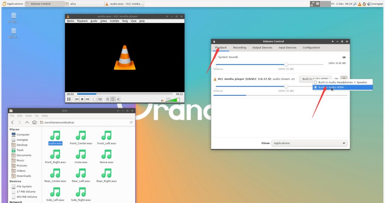
a. 首先打开音量控制界面

b. 播放音频的时候,在 Playback 中会显示播放软件可以使用的音频设备选项, 如下图所示,在这里可以设置需要播放到哪个音频设备
查询 使用命令播放音频的方法
1、耳机接口播放音频测试
1) 首先将耳机插入开发板的耳机孔中

2) 然后可以通过 aplay -l 命令可以查看下 linux 系统支持的声卡设备,从下面的输出可知,card 2 为 es8388 的声卡设备,也就是耳机的声卡设备
orangepi@orangepi:~$ aplay -l
card 0: rockchipdp0 [rockchip-dp0], device 0: rockchip-dp0 spdif-hifi-0 [rockchip-dp0 spdif-hifi-0] Subdevices: 1/1 |
3) 然后使用 aplay 命令播放下系统自带的音频文件,如果耳机能听到声音说明硬件能正常使用
| rangepi@orangepi:~$ aplay -D hw:2,0 /usr/share/sounds/alsa/audio.wav Playing WAVE 'audio.wav' : Signed 16 bit Little Endian, Rate 44100 Hz, Stereo |
2、HDMI 音频播放测试
1) 首先使用 HDMI 转 HDMI 线将 Orange Pi 开发板连接到电视机上(其他的 HDMI 显示器需要确保可以播放音频)
2) 然后查看下 HDMI 的声卡序号,从下面的输出可以知道 HDMI 的声卡为 card 1
orangepi@orangepi:~$ aplay -l
card 0: rockchipdp0 [rockchip-dp0], device 0: rockchip-dp0 spdif-hifi-0 [rockchip-dp0 spdif-hifi-0] Subdevices: 1/1 |
3) 然后使用 aplay 命令播放下系统自带的音频文件,如果 HDMI 显示器或者电视能听到声音说明硬件能正常使用
| orangepi@orangepi:~$ aplay -D hw:1,0 /usr/share/sounds/alsa/audio.wav |
查询 使用命令测试录音的方法
1) 开发板上有板载 MIC,位置如下所示:
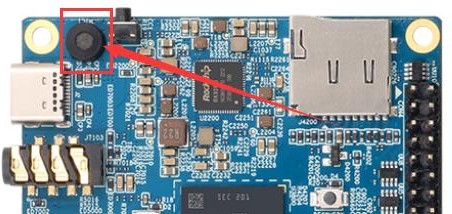
2) 运行 test_record.sh main 命令会通过板载 MIC 录制一段音频,然后播放到 HDMI 和耳机。
| orangepi@orangepi:~$ test_record.sh main Start recording: /tmp/test.wav |
3) 除了板载 MIC,我们还可以通过带 MIC 功能的耳机来录制音频。将带 MIC 功能的耳机插入开发板后,运行 test_record.sh headset 命令会通过耳机录制一段音频, 然后播放到 HDMI 和耳机。
| orangepi@orangepi:~$ test_record.sh headset Start recording: /tmp/test.wav |
26 Pin 接口引脚说明
1) Orange Pi 5 开发板 26 pin 接口引脚的顺序请参考下图
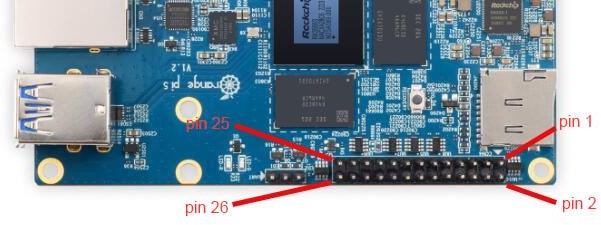
2) Orange Pi 5 开发板 26 pin 接口引脚的功能如下表所示
a. 下面是 26pin 完整的引脚图

b. 下面的表格是上面完整表格左半边部分的图,能看得清楚点

c. 下面的表格是上面完整表格右半边部分的图,能看得清楚点
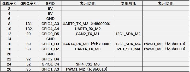
| 上面表格中 pwm 都标出了对应的寄存器的基地址,在查看/sys/class/pwm/中哪个 pwmchip 对应 26pin 排针中哪个 pwm 引脚时很有用。 |
3) 26pin 接口中总共有 17 个 GPIO 口,所有 GPIO 口的电压都是 3.3v
| 关于Linux系统使用说明更详细的资料,你可以在Orange Pi 5用户手册中查阅。 |
Android 12 系统的使用说明
已支持的 Android 版本
| Android 版本 | 内核版本 |
| Android 12 | Linux5.10 |
| Android 12 Box | Linux5.10 |
Android 功能适配情况
| 功能 | Android 12 | Android12 Box |
| USB2.0x2 | OK | OK |
| USB3.0x1 | OK | OK |
| USB Type-C 3.0 | OK | OK |
| DP 显示 | OK | OK |
| M.2 NVMe SSD 启动 | OK | OK |
| M.2 SATA SSD 启动 | OK | OK |
| AP6275P-WIFI | OK | OK |
| AP6275P-蓝牙 | OK | OK |
| GPIO(26pin) | OK | OK |
| UART(26pin) | OK | OK |
| SPI(26pin) | OK | OK |
| I2C(26pin) | OK | OK |
| PWM(26pin) | OK | OK |
| 3pin 调试串口 | OK | OK |
| TF 卡启动 | OK | OK |
| HDMI 视频 | OK | OK |
| HDMI 音频 | OK | OK |
| OV13850 摄像头 | OK | OK |
| OV13855 摄像头 | OK | OK |
| LCD1 | OK | NO |
| LCD2 | OK | NO |
| 千兆网口 | OK | OK |
| 网口状态灯 | OK | OK |
| MIC | OK | OK |
| 耳机播放 | OK | OK |
| 耳机录音 | OK | OK |
| LED 灯 | OK | OK |
| GPU | OK | OK |
| NPU | OK | OK |
| VPU | OK | OK |
| 开关机按键 | OK | OK |
| HDMI CEC 功能 | NO | OK |
USB 无线网卡的使用方法
1) 目前镜像适配的 USB 无线网卡型号如下所示:
| 芯片型号 | 功能 | VID&PID | 适配情况 |
| RTL8821CU | 2.4G +5G WIFI+BT 4.2 | 0bda:c820 | 支持 WIFI、蓝牙和开热点 |
| RTL8723BU | 2.4G WIFI+BT4.0 | 0bda:b720 | 支持 WIFI 和蓝牙功能,不支持开热点 |
| RTL8811CU | 2.4G +5G WIFI | 0bda:c811 | 支持 WIFI 功能和开热点 |
2) 上面三款 USB 无线网卡的图片如下所示:
a. RTL8821CU USB 无线网卡模块的图片如下所示:

b. RTL8723BU USB 无线网卡模块的图片如下所示:
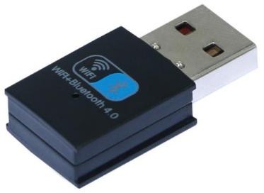
c. RTL8811CU USB 无线网卡模块的图片如下所示:

3) 以上 3 种型号的 USB 无线网卡的测试方法都是相同的,首先需要将 USB 网卡插入开发板的 USB 接口
4) 然后 WIFI 的连接和测试方法请参考 WIFI 的连接测试方法一节
5) 蓝牙的测试请参考 蓝牙的测试方法一节
AP6275P PCIe 网卡的使用方法
1) 首先需要购买一个下图所示的 AP6275P PCIe 网卡

2) 然后将 AP6275P PCIe 网卡插入开发板的 M.2 接口中并固定好

3) 然后给开发板接上 Type-C 接口的电源,并上电
4) 系统启动后,WIFI 的连接和测试方法请参考 WIFI 的连接测试方法一节
5) 蓝牙的测试请参考 蓝牙的测试方法一节
WIFI 的连接测试方法
1) 首先点击进入 Setting

2) 然后选择 Network & internet

3) 然后选择 Internet

4) 然后打开 Wi-Fi 开关

5) 打开 Wi-Fi 后如果一切正常,就可以扫描到附近的 Wi-Fi 热点了

6) 然后选择想连接的 Wi-Fi 后会弹出下图所示的密码输入界面

7) 然后使用键盘输入 Wi-Fi 对应的密码,再使用鼠标点击虚拟键盘中的回车按钮就会开始连接 Wi-Fi 了

8) Wi-Fi 连接成功后的显示如下图所示:
Wi-Fi hospot 的使用方法
1) 首先请确保以太网口已连接网线,并且能正常上网
2) 然后选择 Settings
3) 然后选择 Network & internet
4) 然后选择 Hotspot & tethering
5) 然后选择 Wi-Fi hotspot
6) 然后打开 Wi-Fi hotspot,下图中还可以看到生成的热点的名字和密码,记住它们,在连接热点的时候要用到(如果需要修改热点的名字和密码,需要先关闭 Wi-Fi hotspot,然后才能修改)
7) 此时可以拿出你的手机,如果一切正常,在手机搜索到的 WI-FI 列表中就能找到上图 Hotspot name 下面显示的同名(这里为 AndroidAP_6953)的 WIFI 热点了。然后可以点击 AndroidAP_6953 连接热点,密码在上图的 Hotspot password 下面可以看到
8) 连接成功后显示如下图所示(不同手机界面会有区别,具体界面以你手机显示的为准)。此时就可以在手机上打开一个网页看下能否上网了,如果能正常打开网页, 说明开发板的 WI-FI Hotspot 能正常使用

蓝牙的测试方法
1) 首先点击进入 Setting

2) 然后选择 Connected devices
3) 然后点击 Pair new device 打开蓝牙并开始扫描周围的蓝牙设备

4) 搜索到的蓝牙设备会在 Available devices 下面显示出来

5) 然后点击想要连接的蓝牙设备就可以开始配对了,当弹出下面的界面时,请使用鼠标选择 Pair 选项

6) 这里测试的是开发板和安卓手机蓝牙的配置过程,此时在手机上会弹出下面的确认界面,在手机上也点击配对按钮后就会开始配对过程
7) 配对完成后,可以看到如下图所示的已配对的蓝牙设备

8) 此时可以使用手机蓝牙给开发板发送一张图片,发送后,在开发板的安卓系统中可以看到下面的确认界面,然后点击 Accept 就可以开始接收手机发过来的图片了

9) 开发板 Android 系统蓝牙接收到的图片可以在文件管理器中打开 Download 目录查看

10.1 寸 MIPI 屏幕的使用方法
| 请确保使用的镜像为下面的三个版本的镜像: OrangePi5_RK3588S_Android12_lcd_v1.x.x.img |
1) 首先需要组装好屏幕,请参考 AP6275P PCIe 网卡的使用方法
2) 开发板上有两个 mipi lcd 屏幕的接口,我们定义:
a. lcd1 接口的位置为:
b. lcd2 接口的位置为:

3) 将组装好的屏幕接到 lcd1 或者 lcd2 接口,给板子接通 Type-C 电源,并上电,系统启动后,就可以看到屏幕显示如下图所示

OV13850 和 OV13855 MIPI 摄像头的测试方法
目前开发板支持两款MIPI摄像头,OV13850 和OV13855,具体的图片如下所示:
a. 1300 万MIPI接口的OV13850 摄像头

b. 1300 万MIPI接口的OV13855 摄像头

OV13850 和OV13855 摄像头使用的转接板和FPC排线是一样的,只是两款摄像头接在转接板上的位置不一样。FPC排线如下图所示,请注意FPC排线是有方向的, 标注TO MB那端需要插到开发板的摄像头接口中,标注TO CAMERA那端需要插到摄像头转接板上。

摄像头转接板上总共有 3 个摄像头的接口,同一时间只能接一个使用,如下图所示,其中:
a. 1 号接口接 OV13850 摄像头
b. 2 号接口接 OV13855 摄像头
c. 3 号接口未使用,忽略即可
Orange Pi 5 开发板上总共有 3 个摄像头接口,我们定义 Cam1、Cam2 和 Cam3的位置如下图所示:


摄像头插在开发板的 Cam1 接口的方法如下所示:

摄像头插在开发板的 Cam2 接口的方法如下所示:
摄像头插在开发板的 Cam3 接口的方法如下所示:
安卓系统默认打开的是 Cam1 和 Cam3 的配置,所以如果要使用摄像头,请选择 Cam1 和 Cam3 接口中的一个。连接好摄像头到开发板上后,我们可以使用下面的方法来测试下摄像头:
a. 在桌面中打开相机 APP
b. 然后就能看到摄像头的预览画面了
File:Pi-5-details2-pic63.png
除了单摄外, 我们还可以同时接两个摄像头。需要注意的是,目前测试双摄像头请使用 Cam1 + Cam3 的组合(支持 ov13850 和 ov13855 混搭)。接好双摄后,然后和前面步骤一样,打开摄像头 APP 后即可看到其中一个摄像头的画面。
切换另一个摄像头的方法为:
a. 首先点击右上角的这三个点
File:Pi-5-details2-pic64.png
b. 然后点击下图所示的位置即可切换摄像头
File:Pi-5-details2-pic65.png
在摄像头APP 下图红框所示的区域中按住鼠标然后向右拖动可以调出拍照和摄像的切换界面
File:Pi-5-details2-pic66.png
拍照和摄像的切换界面如下所示,点击 Video 即可切换到录像模式
File:Pi-5-details2-pic67.png
点击下图所示的位置可以进入摄像头的设置界面
File:Pi-5-details2-pic68.png
摄像头的设置界面如下所示:
File:Pi-5-details2-pic69.png
目前测试 OV13850 不支持 4K 录制视频(OV13855 支持),最高只支持 1080p, 录制视频时请在设置中将视频格式切换到 1080p,步骤如下所示:
a. 首先进入摄像头 APP 的设置界面,然后点击 Resolution & quality
File:Pi-5-details2-pic70.png
b. 然后在 Video 中将视频格式设置为 1080p
File:Pi-5-details2-pic71.png
26pin GPIO 口测试
1) 首先点击 wiringOP 图标打开 wiringOP APP
File:Pi-5-details2-pic72.png
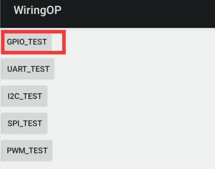
2) wiringOP APP 的主界面显示如下图所示,然后点击 GPIO_TEST 按钮打开 GPIO测试界面
File:Pi-5-details2-pic73.png
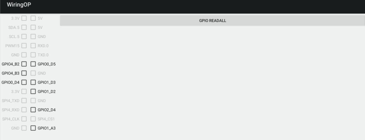
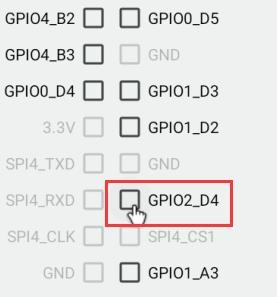
3) GPIO 测试界面如下图所示,左边的两排 CheckBox 按钮跟 26pin 引脚是一一对应的关系。当勾选 CheckBox 按钮时,对应的 GPIO 引脚会被设置为 OUT 模式,引脚电平设置为高电平;当取消勾选时,GPIO 引脚电平设置为低电平;当点击右边的 GPIO READALL 按钮时,可以获取到 wPi 号、GPIO 模式、引脚电平等信息。
File:Pi-5-details2-pic74.png
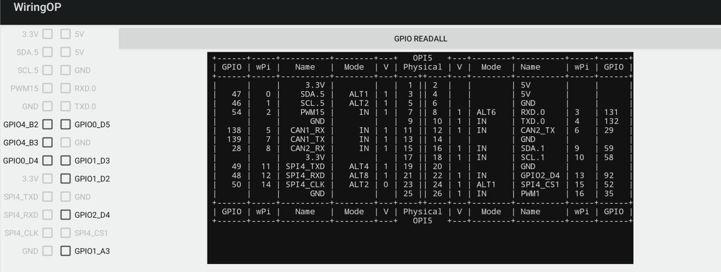
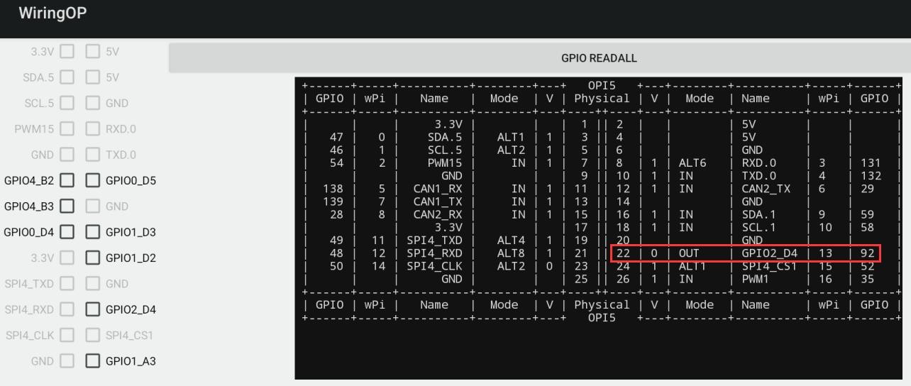
4) 然后点击 GPIO READALL 按钮,输出信息如下图所示:
File:Pi-5-details2-pic75.png
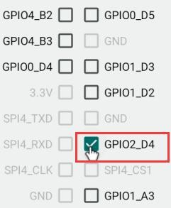
5) 开发板 26pin 中总共有 16 个 GPIO 口可以使用,下面以 7 号引脚——对应 GPIO 为 GPIO1_C6 ——对应 wPi 序号为 2——为例演示如何设置 GPIO 口的高低电平。首先点击 7 号引脚对应的 CheckBox 按钮,当按钮为选中状态时,7 号引脚会设置为高电平,设置完后可以使用万用表测量引脚的电压的数值,如果为 3.3v,说明设置高电平成功
File:Pi-5-details2-pic76.png
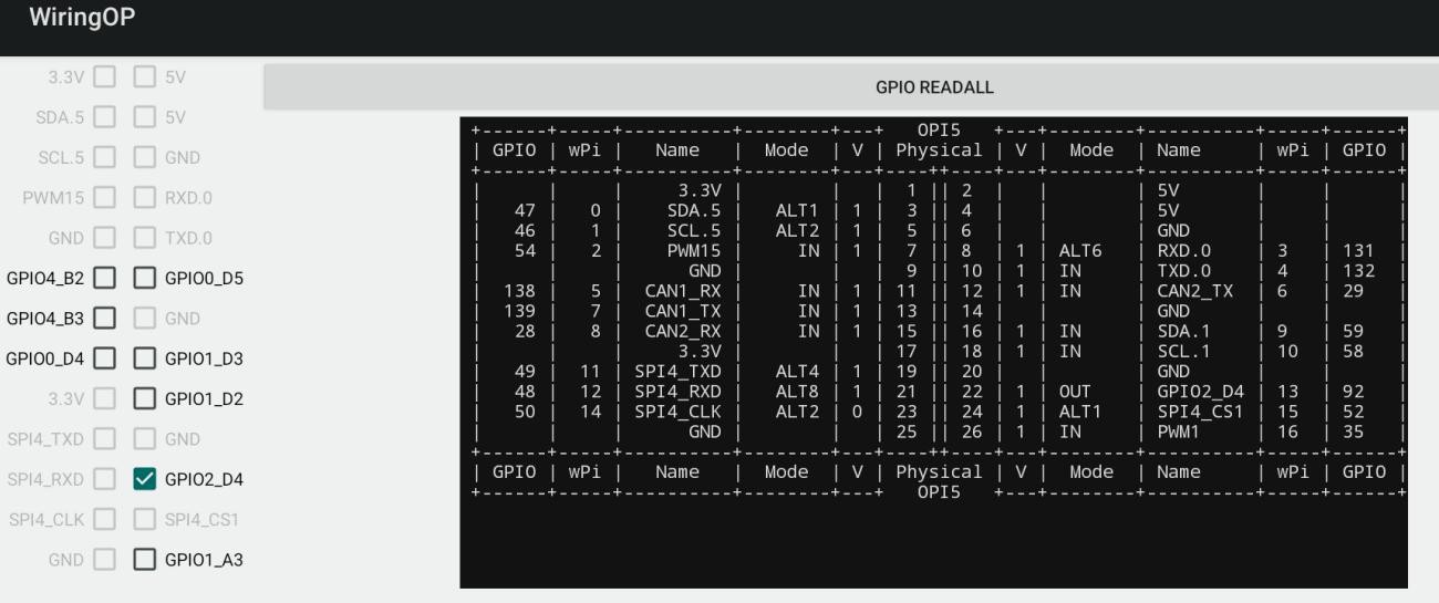
6) 然后点击 GPIO READALL 按钮,可以看到当前的 7 号引脚模式为 OUT,引脚电平为高电平
File:Pi-5-details2-pic77.png
7) 再次点击下图的 CheckBox 按钮取消勾选状态,7 号引脚会设置为低电平,设置完后可以使用万用表测量引脚的电压的数值,如果为 0v,说明设置低电平成功
File:Pi-5-details2-pic78.png
8) 然后点击 GPIO READALL 按钮,可以看到当前的 7 号引脚模式为 OUT,引脚电平为低电平
File:Pi-5-details2-pic79.png
26pin 的 UART 测试
1) Android 中默认只打开了 UART0 一个串口,UART0 在 26pin 的位置如下图所示, 对应的设备节点是/dev/ttyS0
File:Pi-5-details2-pic80.png
2) 首先点击 wiringOP 图标打开 wiringOP APP
File:Pi-5-details2-pic81.png
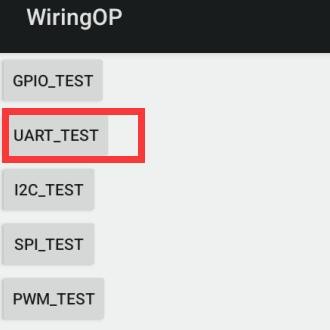
3) wiringOP APP 的主界面显示如下图所示,然后点击 UART_TEST 按钮打开UART测试界面
File:Pi-5-details2-pic82.png
4) APP 的串口测试界面如下图所示
File:Pi-5-details2-pic83.png
5) 接着在编辑框中输入想要设置的波特率,然后点击 OPEN 按钮打开/dev/ttyS0 节点,打开成功后,OPEN 按钮变为不可选中状态,CLOSE 按钮和 SEND 按钮变为可选中状态
File:Pi-5-details2-pic84.png
6) 然后使用杜邦线短接 uart0 的 RXD 和 TXD 引脚
File:Pi-5-details2-pic85.png
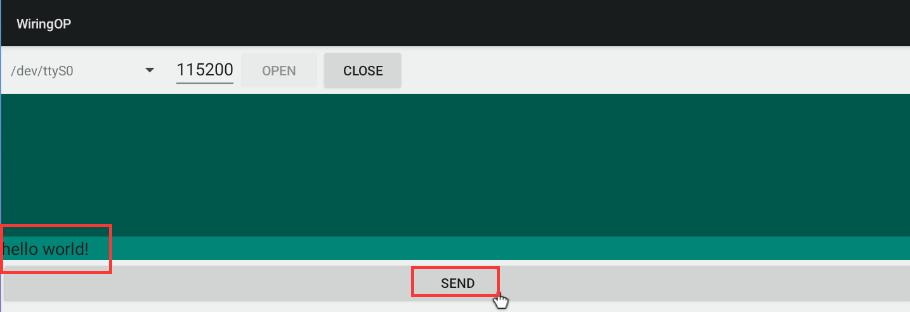
7) 然后可以在下面的发送编辑框中输入一段字符,点击 SEND 按钮开始发送
File:Pi-5-details2-pic86.png
8) 如果一切正常,接收框内会显示已接收到的字符串
File:Pi-5-details2-pic87.png
26pin 的 SPI 测试
1) 由 26pin 接口的原理图可知,Orange Pi 5B 可用的 spi 为 spi4
File:Pi-5-details2-pic88.png
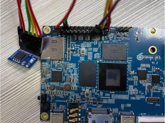
2) 这里通过 w25q64 模块来测试 SPI 接口,首先在 SPI4 接口接入 w25q64 设备
File:Pi-5-details2-pic89.png
3) 然后点击 wiringOP 图标打开 wiringOP APP
File:Pi-5-details2-pic90.png
4) wiringOP APP 的主界面显示如下图所示,点击 SPI_TEST 按钮打开 SPI 的测试界面
File:Pi-5-details2-pic91.png
5) 然后点击 OPEN 按钮初始化 SPI
File:Pi-5-details2-pic92.png
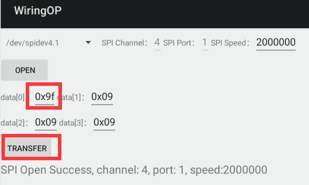
6) 然后填充需要发送的字节,比如读取 w25q64 的 ID 信息,在 data[0]中填入地址0x9f,然后点击 TRANSFER 按钮
File:Pi-5-details2-pic93.png
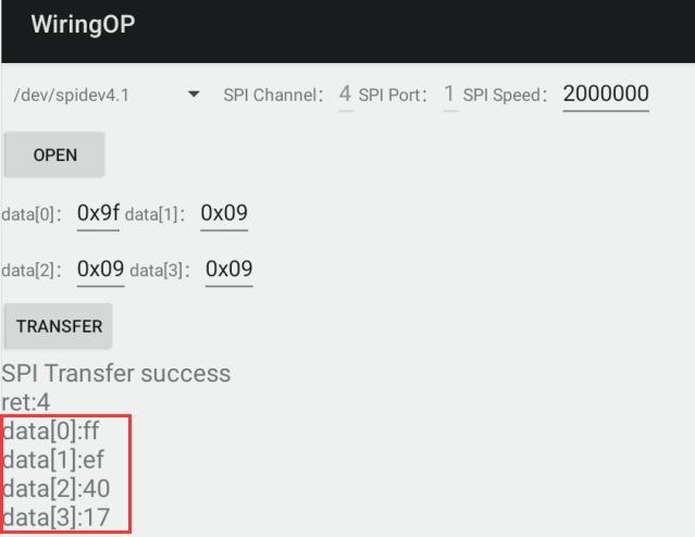
7) 最后 APP 会显示读取到的 ID 信息
File:Pi-5-details2-pic94.png
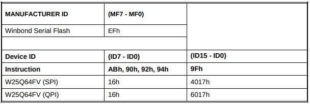
8) w25q64 模块的 MANUFACTURER ID 为 EFh,Device ID 为 4017h,跟上面读取到的值是对应的(h 代表是 16 进制)
File:Pi-5-details2-pic95.png
26pin 的 PWM 测试
1) Android 默认只开启了 PWM15,对应的引脚在 26pin 的所在位置如下图所示
File:Pi-5-details2-pic96.png
2) 首先点击 wiringOP 图标打开 wiringOP APP
File:Pi-5-details2-pic97.png
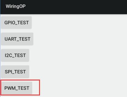
3) 然后在 wiringOP 的主界面点击 PWM_TEST 按钮进入 PWM 的测试界面
File:Pi-5-details2-pic98.png
4) PWM15 对应的基地址是 febf0030 , 这里 pwmchip0 右边显示的刚好就是febf0030.pwm, 如果显示的基地址不对,请点击下拉选项选择其它的 pwmchip,直到右边显示 febf0030 为止
File:Pi-5-details2-pic99.png
5) 然后确认 PWM 的周期,默认的配置是 50000ns,转换为 PWM 频率是 20KHz, 可自行修改,点击开启按钮导出 PWM15
File:Pi-5-details2-pic100.png
6) 然后拖动下面的拖动条,就可以改变 PWM 的占空比,然后勾选 Enable 就可以输出 PWM 波形了
File:Pi-5-details2-pic101.png
7) 然后使用示波器测量开发板 26pin 中的第 7 号引脚就可以看到下面的波形了
File:Pi-5-details2-pic102.png
使用数据线连接 adb 调试
1) 首先准备一根品质良好的 Type-C 数据线
File:Pi-5-details2-pic103.png
2) 然后使用 Type-C 数据线将开发板连接到电脑的 USB 接口中(请同时使用 TypeC电源给开发板供电)
3) 在 Ubuntu PC 上安装 adb 工具
| test@test:~$ sudo apt update test@test:~$ sudo apt -y install adb |
4) 通过下面的命令可以查看识别到的 ADB 设备
| test@test:~$ adb devices List of devices attached |
5) 然后在 Ubuntu PC 上通过 adb shell 就可以登录到 android 系统了
| test@test:~$ adb shell console:/ $ |
6) 执行命令重新挂载 Android 系统
| test@test:~$ adb root test@test:~$ adb remount |
7) 然后就可以传输文件到 Android 系统了
| test@test:~$ adb push example.txt /system/ |
使用网络连接 adb 调试
| 使用网络 adb 无需 USB Typc C 接口的数据线来连接电脑和开发板,而是通过网络来通信,所以首先请确保开发板的有线或者无线网络已经连接好了,然后获取开发板的 IP 地址,后面要用到。 |
1) 确保 Android 系统的 service.adb.tcp.port 设置为 5555 端口号
|
console:/ # getprop | grep "adb.tcp" |
2) 如果 service.adb.tcp.port 没有设置,可以使用下面的命令设置网络 adb 的端口号
| console:/ # setprop service.adb.tcp.port 5555 console:/ # stop adbd |
3) 在 Ubuntu PC 上安装 adb 工具
| test@test:~$ sudo apt update test@test:~$ sudo apt install -y adb |
4) 然后在 Ubuntu PC 上连接网络 adb
| test@test:~$ adb connect 192.168.1.xxx (IP 地址需要修改为开发板的 IP 地址) daemon not running; starting now at tcp:5037 test@test:~$ adb devices |
5) 然后在 Ubuntu PC 上通过 adb shell 就可以登录到 android 系统了
| test@test:~$ adb shell console:/ # |
Android Box 测试过的 2.4G USB 遥控器
1) 目前测试过的一款 2.4G USB 遥控器如下图所示
a. 包含一个遥控器
File:Pi-5-details2-pic104.png
b. 一个 USB 无线接收器
File:Pi-5-details2-pic105.png
2) Android Box 系统无需任何配置,插上就可以用了
Android Box 系统 HDMI CEC 功能的使用方法
|
HDMI CEC 允许用户只用一个遥控器,就能通过 HDMI 控制所有连接的设备, 基于这个功能,我们用电视机的遥控器就可以控制开发板。 |
1) 首先将开发板通过 HDMI 线连接到电视,然后上电启动
2) 然后在电视的设置中开启 HDMI CEC 功能,不同电视开启方式可能有差异,这里以小米电视为例,按下遥控器的菜单键,然后选中 CEC 遥控并按下确认键
File:Pi-5-details2-pic106.png
3) 然后选择“开”就可以打开 HDMI CEC 遥控
File:Pi-5-details2-pic107.png
4) 此时就可以通过电视的遥控器控制开发板的 Android Box 系统了