Orange Pi RV2
Orange Pi RV2
User Manual

Contents
- 1 Basic characteristics of Orange Pi RV2
- 2 Introduction to using the development board
- 2.1 Prepare the necessary accessories
- 2.2 Download the image of the development board and related materials
- 2.3 Method of burning Linux image to TF card based on Windows PC
- 2.4 Method for burning Linux images to TF cards based on Ubuntu PC于Ubuntu PC
- 2.5 Method for burning Linux images to eMMC
- 2.6 Method for burning Linux images to SPIFlash+NVMe SSD
- 2.7 Method for burning Linux images to SPIFlash+USB storage devices
- 2.8 Launch the Orange Pie development board
- 2.9 How to use the debug serial port
- 2.10 Instructions for using the 5V pin in the 26pin interface of the development board to supply power
- 3 Ubuntu Server and Gnome Desktop System Instructions
- 3.1 Supported Linux image types and kernel versions
- 3.2 Linux 6.6 system compatibility
- 3.3 Linux command format description in this manual
- 3.4 Linux system login instructions
- 3.5 Onboard LED light test instructions
- 3.6 Network connection test
- 3.7 SSH remote login development board
- 3.8 How to upload files to the Linux system of the development board
- 3.9 HDMI test
- 3.10 How to use Bluetooth
- 3.11 USB interface test
- 3.12 Audio Test
- 3.13 Temperature sensor
- 3.14 26 Pin Interface Pin Description
- 3.15 How to install wiringOP
- 3.16 26pin interface GPIO, I2C, UART, SPI, CAN and PWM test
- 3.17 Installation and use of wiringOP-Python
- 3.18 Hardware watchdog test
- 3.19 How to use Docker
- 3.20 Test of some programming languages supported by Linux system
- 3.21 How to install kernel header files
- 3.22 How to use 2.10.1 inch MIPI LCD screen
- 3.23 Test methods for OV13850 and OV13855 MIPI cameras
- 3.24 Methods for Running Large Models
- 3.25 Use of DeepSeek
- 3.26 Methods for shutting down and restarting the development board
- 4 Linux SDK——orangepi-build usage instructions
- 5 Appendix
Basic characteristics of Orange Pi RV2
What is Orange Pi RV2
OrangePi RV2 is a cost-effective RISC-V development board that adopts a CPU integrated AI technology architecture and is equipped with an RISC-V eight core processor. It provides universal computing power with 2TOPS CPU integration and supports rapid deployment of AI model algorithms. Equipped with 2GB/4GB/8GB LPDDR4X, supporting eMMC modules (16GB/32GB/64GB/128GB optional), Wi Fi 5.0+BT 5.0, and BLE support.
OrangePi RV2 has a wide range of interfaces, including HDMI output, GPIO interface USB2.0, USB3.0, Gigabit Ethernet port, 3.5mm headphone jack, equipped with two M.2 M-Key slots (PCIe 2.0 2-Lane), supports installation of NVMe solid-state drives.
OrangePi RV2 is exquisite, small and powerful, and can be widely used in NAS, commercial electronic products, smart robots, smart home, industrial control, edge computing, etc. Supports the Ubuntu 24.04 operating system.
Purpose of Orange Pi RV2
We can use it to achieve:
- A Linux desktop computer.
- A Linux network server.
Of course, there are many other features as well. With a powerful ecosystem and various expansion accessories, Orange Pi can help users easily achieve delivery from creativity to prototype to mass production. It is an ideal creative platform for makers, dreamers, and hobbyists.
Hardware Features of Orange Pi RV2
| Introduction to Hardware Features | |
| Processor | • 8 core 64 bit RISC-V processor
• 2 TOPS AI computing power |
| Video | • 1 * HDMI 1.4, maximum support 1080 @ 60Hz
• 1 * MIPI DSI 4Lane |
| Memory | 2GB/4GB/8GB(LPDDR4X) |
| Camera | • 2 * MIPI CSI 4Lane |
| PMU | P1 |
| Onboard storage | • eMMC socket, capable of connecting external eMMC modules
• 16MB QSPI Nor FLASH • MicroSD (TF) Card Slot • 2 * PCIe2.0 M.2 M-KEY (SSD) Slot |
| Ethernet | 2 * Gigabit Ethernet port(YT8531C ) |
| WIFI+BT | • Onboard Wi Fi 5+BT 5.0/BLE module: AP6256
• Wi-Fi interface:SDIO3.0 • BT interface:UART/PCM |
| Audio | • 3.5mm headphone jack audio input/output
• 1 * HDMI output |
| PCIe M.2 M-KEY | • 2 * PCIe 2.0 x 2 lanes, used for connecting NVMe SSD solid state drives |
| USB interface | • 1 * USB 2.0 supports Device or HOST mode
• 3 * USB3.0 HOST |
| 26pin extension pin | Used for expanding UART, PWM, I2C, SPI, CAN, and GPIO interfaces |
| Debug UART | 3 PIN debugging serial port |
| LED lamp | 1 * Power light, 1 * Status light |
| Key | 1 * BOOT button, 1 * power on/off button |
| Power supply | Type-C interface power supply 5V/5A |
| Supported operating systems | Operating systems such as Ubuntu 24.04 |
| Introduction to appearance specifications | |
| Product size | 89mm*56mm |
| Weight | 60g |
| File:Convert ed\OrangePi RV2 X 1 User Manual v1. 0.1/media/image1. png{width=“0.255 55555555555554in” h eight=“0.27638888 88888889in”}range Pi™ is a registered trademark of Shenzhen Xunlong Software Co., Ltd. |
Top and Bottom Views of Orange Pi RV2
top view:

Bottom level view:

Interface details diagram of Orange Pi RV2


The diameter of the four positioning holes is 2.7mm.
Introduction to using the development board
Prepare the necessary accessories
TF card, a high-speed flash card with a minimum capacity of 16GB (recommended 32GB or above) and class10 or above.

TF card reader, used to burn images onto TF cards.

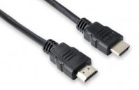
HDMI interface display.

HDMI to HDMI connection cable, used to connect the development board to an HDMI monitor or TV for display.
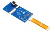
10.1-inch MIPI screen, used to display the system interface of the development board (this screen includes adapter board and universal OPi5Plus/OPi5/OPi5Pro/OPi5Max/OPi5Ultra/OPiRV2).

For the Orange Pi RV2 power adapter, it is recommended to use a 5V/5A Type-C power supply.

The Type-C power interface of the development board does not support PD negotiation function and only supports a fixed 5V voltage input.
A USB interface mouse and keyboard, as long as it is a standard USB interface mouse and keyboard, can be used to control the Orange Pi development board.

USB camera.

A 5V cooling fan. As shown in the figure below, the development board is equipped with an interface for connecting a cooling fan, with the interface specification being a 2pin 1.25mm pitch.
The fan on the development board can be adjusted for speed and on/off through PWM.
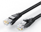
100Mbps or 1G Ethernet cable, used to connect the development board to the Internet.
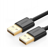
USB 2.0 male to male data cable, used for burning images and using ADB functions.
OV13850 camera with 13 million MIPI interface.
OV13855 camera with 13 million MIPI interface.
When using the serial port debugging function, a 3.3V USB to TTL module and DuPont cable are required to connect the development board and computer.
![G7U7JZX(V`L$`A6864]38$P](/orangepiwiki/images/thumb/8/81/OrangePi_RV2_X1_User_Manual_v1.0.1_image19.png/215px-OrangePi_RV2_X1_User_Manual_v1.0.1_image19.png)

A personal computer with Ubuntu and Windows operating systems installed.


![G7U7JZX(V`L$`A6864]38$P](/orangepiwiki/index.php/File:OrangePi_RV2_X1_User_Manual_v1.0.1_image19.png)

| 1 | Ubuntu22.04 PC | Optional, used for compiling Linux source code |
| 2 | Windows PC | Used for burning Linux images |
- The download link for the Chinese version of the material is:
http://www.orangepi.cn/html/hardWare/computerAndMicrocontrollers/details/Orange-Pi-RV2.html
The download link for the English version of the material is:
http://www.orangepi.online/html/hardWare/computerAndMicrocontrollers/details/Orange-Pi-RV2.html
The information mainly includes
Linux source code:Save on Github.
User manual and schematic diagram:Save on Baidu Cloud Drive and Google Cloud Drive.
Official tools:This mainly includes the software required during the use of the development board.
Ubuntu image:Save on Baidu Cloud Drive and Google Cloud Drive.
OpenWRT image:Save on Baidu Cloud Drive and Google Cloud Drive.
Method of burning Linux image to TF card based on Windows PC
Note that the Linux image referred to here specifically refers to Linux distribution images such as Debian, Ubuntu, OpenWRT, or OPi OS Arch downloaded from the Orange Pi data download page.
Method of burning Linux images using BalenaEtcher
- Firstly, prepare a 16GB or larger TF card with a transfer speed of class10 or above. It is recommended to use TF cards from brands such as SanDisk.
- Then use a card reader to insert the TF card into the computer.
- Download the compressed file of the Linux operating system image that you want to burn from the Orange Pi's download page, and then use decompression software to decompress it. In the decompressed file, the file ending with ".img" is the operating system image file, which is usually over 2GB in size.
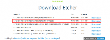
- Then download the Linux image burning software - balenaEtcher, from the following download link:
- After entering the balenaEtcher download page, clicking the green download button will jump to the software download location.

Then you can choose to download the Portable version of balenaEtcher software, which does not require installation and can be used by double clicking.
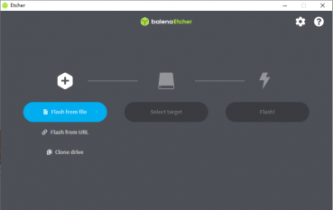
If you are downloading a version of balenaEtcher that requires installation, please install it first before using it. If you download the Portable version of balenaEtcher, simply double-click to open it. The interface of balenaEtcher after opening is shown in the following figure:


When opening balenaEtcher, if prompted with the following error:

Please select balenaEtcher and right-click, then choose to run as administrator.择balenaEtcher

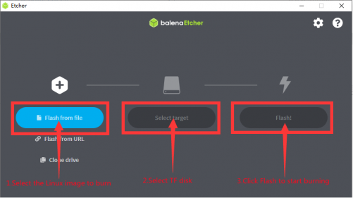
The specific steps for burning a Linux image using balenaEtcher are as follows:
Firstly, select the path of the Linux image file to be burned.
Then select the drive letter of the TF card.。
Finally, clicking Flash will start burning the Linux image onto the TF card.
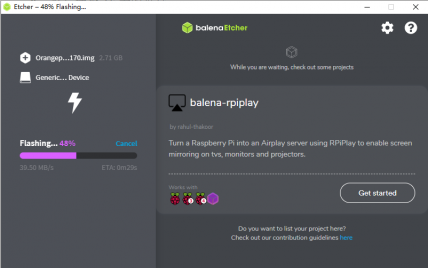
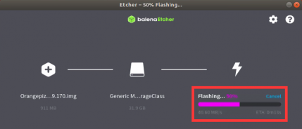
The interface displayed during the process of burning a Linux image by balenaEtcher is shown in the following figure. In addition, the progress bar displaying purple indicates that the Linux image is being burned to the TF card.
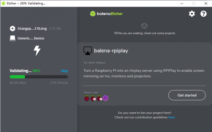
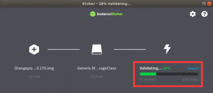
After the Linux image is burned, balenaEtcher will also verify the image burned to the TF card by default to ensure that there are no problems during the burning process. As shown in the following figure, a green progress bar indicates that the image has been burned and balenaEtcher is verifying the burned image.
After successful burning, the display interface of balenaEtcher is shown in the following figure. If a green indicator icon is displayed, it indicates that the image burning is successful. At this time, you can exit balenaEtcher, then unplug the TF card and insert it into the TF card slot of the development board for use.


Method for burning Linux images to TF cards based on Ubuntu PC于Ubuntu PC
Note that the Linux image referred to here specifically refers to Linux distribution images such as Debian, Ubuntu, OpenWRT, or OPi OS Arch downloaded from the Orange Pi data download page. Ubuntu PC refers to a personal computer with the Ubuntu system installed.
- Firstly, prepare a 16GB or larger TF card with a transfer speed of class10 or above. It is recommended to use TF cards from brands such as SanDisk.
- Then use a card reader to insert the TF card into the computer.
- Download the balenaEtcher software from the following link:
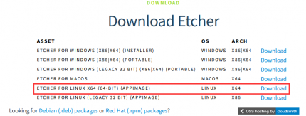
- After entering the balenaEtcher download page, clicking the green download button will jump to the software download location.
Then choose to download the Linux version of the software.
Download the compressed file of the Linux operating system image that you want to burn from the Orange Pi's download page, and then use decompression software to decompress it. In the decompressed file, the file ending with ".img" is the operating system image file, which is usually over 2GB in size.
The decompression command for the compressed file ending in 7z is as follows:
test@test:~$ 7z x orangepirv2_1.0.0_ubuntu_noble_desktop_gnome_linux6.6.63.7z
test@test:~$ ls orangepirv2_1.0.0_ubuntu_noble_desktop_gnome_linux6.6.63.*
orangepirv2_1.0.0_ubuntu_noble_desktop_gnome_linux6.6.63.7z orangepirv2_1.0.0_ubuntu_noble_desktop_gnome_linux6.6.63.sha #Verification and file
orangepirv2_1.0.0_ubuntu_noble_desktop_gnome_linux6.6.63.img #image file
After decompressing the image, you can first use the sha256sum -c *.sha command to calculate if the checksum is correct. If the prompt is successful, it means that the downloaded image is correct and can be safely burned to the TF card. If the prompt is that the checksum does not match, it means that there is a problem with the downloaded image. Please try downloading it again.
test@test:~$ sha256sum -c *.sha
orangepirv2_1.0.0_ubuntu_noble_desktop_gnome_linux6.6.63.img: OK
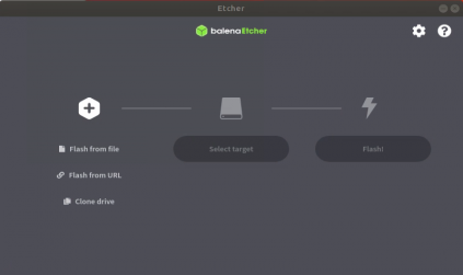
Then double-click balenaEtcher-1.5.109-x64.AppImage on the graphical interface of Ubuntu PC to open BalenaEtcher (no installation required). The interface displayed after opening BalenaEtcher is shown in the following figure.
The specific steps for burning a Linux image using balenaEtcher are as follows:
Firstly, select the path of the Linux image file to be burned.
Then select the drive letter of the TF card.
Finally, clicking Flash will start burning the Linux image onto the TF card.
The interface displayed during the process of burning a Linux image by balenaEtcher is shown in the following figure. In addition, the progress bar displaying purple indicates that the Linux image is being burned to the TF card.


After the Linux image is burned, balenaEtcher will also verify the image burned to the TF card by default to ensure that there are no problems during the burning process. As shown in the following figure, a green progress bar indicates that the image has been burned and balenaEtcher is verifying the burned image.
After successful burning, the display interface of balenaEtcher is shown in the following figure. If a green indicator icon is displayed, it indicates that the image burning is successful. At this time, you can exit balenaEtcher, then unplug the TF card and insert it into the TF card slot of the development board for use.


Method for burning Linux images to eMMC
Note that the development board can be launched through TF card or eMMC, with TF card having higher priority than eMMC. That is to say, if the development board is inserted with a TF card and there is a system in the TF card, the system in the TF card will be started by default instead of the system in eMMC.
The development board has reserved an expansion interface for the eMMC module. Before burning the system to eMMC, it is necessary to purchase an eMMC module that matches the eMMC interface of the development board. Then install the eMMC module onto the development board. The method of inserting the eMMC module into the development board is as follows:


Burning a Linux image to eMMC requires the use of a TF card, so the first step is to burn the Linux image onto the TF card, and then use the TF card to start the development board and enter the Linux system. The method of burning a Linux image to a TF card can be found in the two sections: the method of burning a Linux image to a TF card based on Windows PC and the method of burning a Linux image to a TF card based on Ubuntu PC.
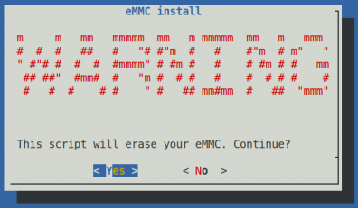
Then run the nand-sata-install script, remember to add sudo privileges
orangepi@orangepi:~$ sudo nand-sata-install
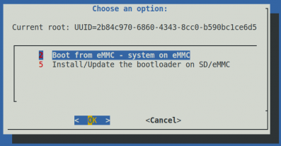
Then select 2 Boot from eMMC - sytem on eMMC
Then a warning will pop up, and the script will erase all data on eMMC. Select <Yes> to continue
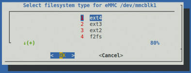
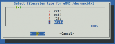
Then it will prompt to select the type of file system, supporting five file systems: ext2/3/4, f2fs, and btrfs
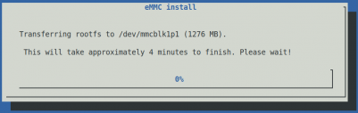
Then it will start formatting eMMC, and after formatting eMMC, it will start burning Linux images into eMMC
After burning, the following options will be prompted, you can choose <Power off> to shut down directly

Then unplug the TF card and power it on again, and the linux system in eMMC will start up


Method for burning Linux images to SPIFlash+NVMe SSD
Firstly, it is necessary to prepare an NVMe SSD solid state drive with a PCIe interface specification of PCIe2.0x2 for the M.2 slot on the development board.

Then insert the NVMe SSD into the M.2 PCIe interface of the development board (note that currently only the M.2 slot on the back supports booting) and secure it in place.
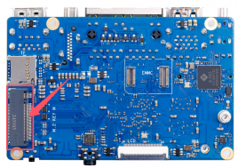
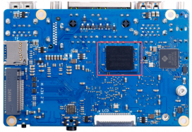
The position of SPI Flash on the development board is shown in the following figure, and no other settings are required before starting to burn.
Burning the image to SPIFlash+NVMe SSD requires the use of a TF card, so the first step is to burn the Linux image onto the TF card, and then use the TF card to boot the development board into the Linux system. The method of burning a Linux image to a TF card can be found in the two sections: the method of burning a Linux image to a TF card based on Windows PC and the method of burning a Linux image to a TF card based on Ubuntu PC.
After starting the Linux system with a TF card, you can burn the image to SPI Flash+NVMe SSD.
First, create a partition for NVMe SSD.
orangepi@orangepi:~$ sudo parted /dev/nvme0n1 mklabel gpt mkpart primary \
ext4 8192s 100%
Then run nand-sata-install, remember to add sudo privileges for regular users.
orangepi@orangepi:~$ sudo nand-sata-install
Then select 4 Boot from SPI - system on SATA, USB or NVMe。


- Then press enter to confirm

- Then select <Yes>。

- Then it will prompt to select the type of file system.

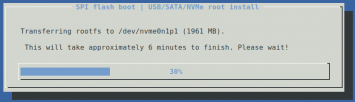
Then it will start formatting the NVMe SSD, and after formatting is complete, it will start burning the system into the NVMe SSD.
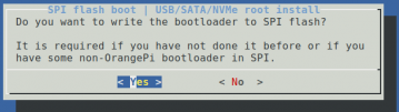
Then please be patient and wait for the burning to complete. After burning, you will be prompted whether to burn the bootloader to SPI Flash, and then select <Yes>. (If you do not want to replace the factory bootloader, you can also choose No.)
After burning, the following options will be prompted, you can choose <Power off>to shut down directly


Method for burning Linux images to SPIFlash+USB storage devices
Note that the Linux image referred to here specifically refers to Linux distribution images such as Debian, Ubuntu, OpenWRT, or OPi OS Arch downloaded from the Orange Pi data download page.
- Firstly, it is necessary to prepare a USB storage device, such as a USB flash drive.
- Then please refer to the instructions in two sections: the method of burning Linux images to TF cards based on Windows PC and the method of burning Linux images to TF cards based on Ubuntu PC to burn Linux images to USB storage devices. There is no difference between burning a Linux image to a USB storage device and burning a Linux image to a TF card (when the TF card is inserted into the card reader, the card reader is actually equivalent to a USB flash drive).
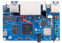
- Then insert the USB storage device that has burned the Linux system into the USB interface of the development board. Note that only the three blue USB 3.0 interfaces shown in the following figure support booting the Linux system, and the white USB 2.0 interface does not support it.

The position of SPI Flash on the development board is shown in the following figure. SPI Flash will burn the program before leaving the factory. If it is not formatted by itself, the following burning steps can be skipped.

Burning the u-boot image to SPIFlash requires the use of a TF card, so the first step is to burn the Linux image onto the TF card, and then use the TF card to boot the development board into the Linux system. The method of burning a Linux image to a TF card can be found in the two sections: the method of burning a Linux image to a TF card based on Windows PC and the method of burning a Linux image to a TF card based on Ubuntu PC.
After starting the Linux system with a TF card, you can burn the u-boot image to SPI Flash.
First, run nand-sata-install. Ordinary users should remember to grant sudo privileges.
orangepi@orangepi:~$ sudo nand-sata-install
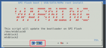
Then select 7 Install/Update ther bootloader on SPI Flash。

- Then select <Yes>。

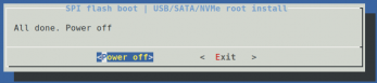
- Then please be patient and wait for the burning to complete. After the burning is completed, the following will be displayed (a 'Done' will appear in the bottom left corner):

At this point, you can use the poweroff command to shut down. Then please unplug the TF card and press the power button briefly to start the linux system in the SPIFlash+USB storage device.
After starting the system in the USB storage device, use the df -h command to see the actual capacity of the USB storage device.
orangepi@orangepi:~$ df -h
Filesystem Size Used Avail Use% Mounted on
udev 3.8G 8.0K 3.8G 1% /dev
tmpfs 769M 588K 769M 1% /run
/dev/sda2 15G 1.6G 13G 11% /
tmpfs 3.8G 0 3.8G 0% /dev/shm
tmpfs 5.0M 4.0K 5.0M 1% /run/lock
/dev/zram2 3.7G 60K 3.5G 1% /tmp
/dev/sda1 256M 111M 146M 44% /boot
/dev/zram1 194M 9.0M 171M 5% /var/log
tmpfs 769M 0 769M 0% /run/user/1000
Launch the Orange Pie development board
- Insert the TF card with the burned image into the TF card slot of the Orange Pie development board. If the SPIFlash+NVMe SSD or eMMC module has already burned the image, there is no need to insert the TF card. Just make sure that the NVMe SSD or eMMC module is properly inserted into the development board.
- The development board has an HDMI interface, which can be connected to a TV or HDMI monitor through an HDMI to HDMI cable. If you purchase an LCD screen, you can also use the LCD screen to display the system interface of the development board.
- Connect a USB mouse and keyboard to control the Orange Pie development board.
- The development board has an Ethernet port that can be plugged into a network cable for internet access.
- Connect a high-quality power adapter with a 5V/4A or 5V/5A USB Type-C interface.
Remember not to insert a power adapter with a voltage output greater than 5V, as it may burn out the development board.
Many unstable phenomena during the power on startup process of the system are basically caused by power supply problems, so a reliable power adapter is very important. If you notice continuous restarts during the startup process, please replace the power supply or Type-C data cable and try again.
The Type-C power interface does not support PD negotiation.
Also, please do not connect the USB port of the computer to power the development board.
Then turn on the power adapter switch. If everything is normal, the HDMI monitor or LCD screen will be able to see the system startup screen.
If you want to view the system's output information by debugging the serial port, please connect the development board to the computer using a serial port cable. For the method of connecting the serial port, please refer to the section on debugging serial port usage.
How to use the debug serial port
Connection Instructions for Debug Serial Port
First, you need to prepare a 3.3V USB to TTL module, and then insert the USB interface of the USB to TTL module into the USB interface of the computer.

The corresponding relationship between the debugging serial port GND, RXD and TXD pins of the development board is shown in the figure below:
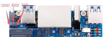
The GND, TXD and RXD pins of the USB to TTL module need to be connected to the debug serial port of the development board through DuPont cables.
Connect the GND of the USB to TTL module to the GND of the development board.
Connect the RX of the USB to TTL module to the TX of the development board.
Connect the TX of the USB to TTL module to the RX of the development board.
The schematic diagram of connecting the USB to TTL module to the computer and the Orange Pi development board is as follows:

The TX and RX of the serial port need to be cross-connected. If you don't want to carefully distinguish the order of TX and RX, you can connect the TX and RX of the serial port randomly. If there is no output in the test, then swap the order of TX and RX. In this way, there will always be one order that is correct.


How to use the debugging serial port on Ubuntu platform
There are many serial port debugging software that can be used under Linux, such as putty, minicom, etc. The following demonstrates how to use putty.
First, insert the USB to TTL module into the USB port of the Ubuntu computer. If the USB to TTL module is connected and recognized normally, you can see the corresponding device node name under /dev of the Ubuntu PC. Remember this node name, which will be used when setting up the serial port software later.
test@test:~$ ls /dev/ttyUSB*
/dev/ttyUSB0
Then install putty on your Ubuntu PC using the command below.
test@test:~$ sudo apt-get update
test@test:~$ sudo apt-get install -y putty
Then run putty and remember to add sudo permissions.
test@test:~$ sudo putty
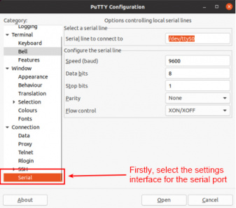
After executing the putty command, the following interface will pop up.
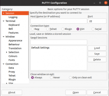
First select the serial port settings interface.
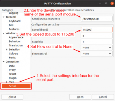
Then set the parameters of the serial port.
Set Serial line to connect to to /dev/ttyUSB0(change to the corresponding node name, usually /dev/ttyUSB0).
Set Speed(baud) to 115200 (the baud rate of the serial port).
Set Flow control to None.
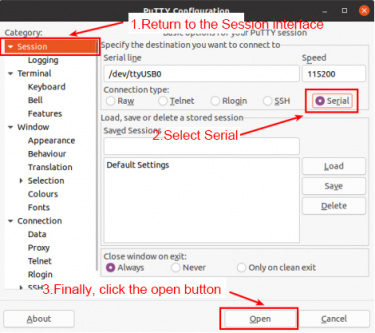
After completing the settings on the serial port settings interface, return to the Session interface.
a. First select Connection type as Serial.
b. Then click the Open button to connect to the serial port.
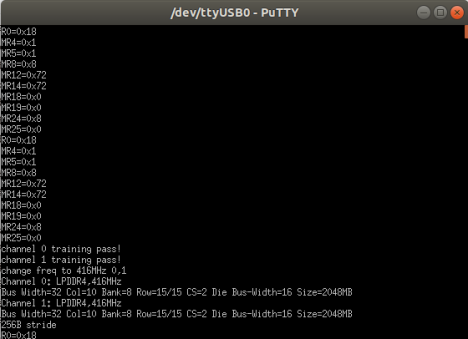
After starting the development board, you can see the log information output by the system from the opened serial port terminal.


How to use the debug serial port on Windows platform
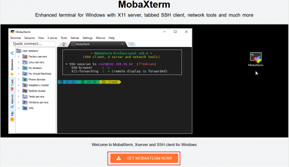
There are many serial port debugging software that can be used under Windows, such as SecureCRT, MobaXterm, etc. The following demonstrates how to use MobaXterm. This software has a free version and can be used without purchasing a serial number.
Download MobaXterm.
Download MobaXterm from the following URL:
Go to the MobaXterm download page and click GET XOBATERM NOW!.
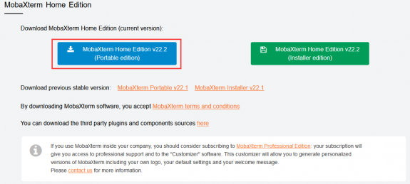
Then choose to download the Home version.

Then select the Portable version. After downloading, there is no need to install it. You can use it directly by opening it.
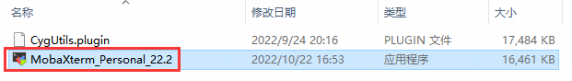
After downloading, use decompression software to decompress the downloaded compressed package to get the executable software of MobaXterm, and then double-click to open it.
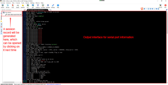
After opening the software, the steps to set up the serial port connection are as follows


Open the session settings interface.
Select the serial port type.
Select the serial port number (select the corresponding port number according to the actual situation). If you cannot see the port number, please use Driver Software to scan and install the USB to TTL serial port chip driver.
Select the serial port baud rate as 115200.
Finally, click the "OK" button to complete the settings.

Click the "OK" button to enter the following interface. Now start the development board and you can see the output information of the serial port.

Instructions for using the 5V pin in the 26pin interface of the development board to supply power
The power supply method we recommend for the development board is to use a 5V/5A Type C interface power cord plugged into the Type-C power interface of the development board for power supply. If you need to use the 5V pin in the 26pin interface to power the development board, please make sure that the power cord and power adapter used can meet the power supply requirements of the development board. If there is any unstable use, please switch back to Type-C power supply.
First, you need to prepare a power cord as shown in the figure below.

The power cord shown in the picture above can be purchased. Please search and purchase it by yourself.
Use the 5V pin in the 26-pin interface to power the development board. The connection method of the power line is as follows:

The USB A port of the power cable shown in the figure above needs to be plugged into the 5V/5A power adapter connector (please do not plug it into the USB port of the computer for power supply).
The red DuPont cable needs to be plugged into the 5V pin of the 26-pin development board.
The black DuPont cable needs to be plugged into the GND pin of the 26-pin interface.
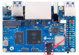
The positions of the 5V pin and GND pin of the 26-pin interface in the development board are shown in the figure below. Remember not to connect them in reverse.


Ubuntu Server and Gnome Desktop System Instructions
Supported Linux image types and kernel versions
| Linux Image Type | Kernel version | Server Edition | Desktop version |
| Ubuntu 24.04 - Noble | Linux6.6 | Support | Support |
Linux 6.6 system compatibility
| Function | Ubuntu24.04 |
| USB2.0x1 | OK |
| USB3.0x3 | OK |
| M.2 M-Key slot x2 | OK |
| M.2 NVMe SSD boot | OK |
| USB boot system | OK |
| WIFI | OK |
| Bluetooth | OK |
| GPIO(26pin) | OK |
| UART(26pin) | OK |
| SPI(26pin) | OK |
| I2C(26pin) | OK |
| CAN(26pin) | OK |
| PWM(26pin) | OK |
| 3pin debug serial port | OK |
| TF card startup | OK |
| HDMI Video | OK |
| HDMI Audio | OK |
| OV13850 Camera | OK(Does not support 3A) |
| OV13855 Camera | OK |
| LCD | OK |
| Gigabit Ethernet port x2 | OK |
| Network port status light | OK |
| Headphone playback | OK |
| Headphone Recording | OK |
| RTC | OK |
| LED Light | OK |
| GPU | OK |
| VPU | OK |
| Power button | OK |
| Watchdog test | OK |
| Chromium hard decoding video | OK |
| MPV hard decoding video playback | OK |
Linux command format description in this manual
All commands in this manual that need to be entered in the Linux system will be framed with the following boxes.
As shown below, the contents in the yellow box indicate the contents that require special attention, except for the commands inside.
Description of the prompt type before the command.
The prompt before the command refers to the content in the red box below. This part is not part of the Linux command, so when entering a command in the Linux system, please do not enter the content in red font.
orangepi@orangepi:~$ sudo apt update
root@orangepi:~# vim /boot/boot.cmd
test@test:~$ ssh [email protected].xxx
root@test:~# ls
orangepi@orangepi:~$ The prompt indicates that this command is entered in the Linux system of the development board. The $ at the end of the prompt indicates that the current user of the system is a common user. When executing privileged commands, sudo is required.
root@orangepi:~# The prompt indicates that this command is entered in the Linux system of the development board. The # at the end of the prompt indicates that the current user of the system is the root user and can execute any command he wants.
test@test:~$ The prompt indicates that this command is entered in an Ubuntu PC or Ubuntu virtual machine, not in the Linux system of the development board. The $ at the end of the prompt indicates that the current user of the system is a normal user. When executing privileged commands, you need to add sudo.
root@test:~# The prompt indicates that this command is entered in an Ubuntu PC or Ubuntu virtual machine, not in the Linux system of the development board. The # at the end of the prompt indicates that the current user of the system is the root user and can execute any command he wants.
What are the commands that need to be entered?
As shown below, the bold black part is the command that needs to be entered, and the content below the command is the output (some commands have output, some may not). This part does not need to be entered.
root@orangepi:~# cat /boot/orangepiEnv.txt
verbosity=7
bootlogo=false
console=serial
As shown below, some commands cannot fit in one line and will be placed on the next line. The bold black parts are the commands that need to be entered. When these commands are entered on one line, the "\" at the end of each line needs to be removed, as it is not part of the command. In addition, there are spaces between different parts of the command, so please do not miss them.
orangepi@orangepi:~$ echo \
"deb [arch=$(dpkg --print-architecture) \
signed-by=/usr/share/keyrings/docker-archive-keyring.gpg] \
https://download.docker.com/linux/debian \
$(lsb_release -cs) stable" | sudo tee /etc/apt/sources.list.d/docker.list > /dev/null
Linux system login instructions
Linux system default login account and password
| Account | Password |
| root | orangepi |
| orangepi | orangepi |
Please note that when you enter the password, the specific content of the password will not be displayed on the screen. Please do not think that there is any malfunction. Just press Enter after entering it.
If you get an error message when entering the password, or there is a problem with the ssh connection, please note that as long as you are using the Linux image provided by Orange Pi, do not doubt that the password above is incorrect, but look for other reasons.
How to set up automatic login for Linux system terminal
The Linux system automatically logs in to the terminal by default, and the default login username is orangepi.
Use the following command to set the root user to automatically log in to the terminal.
orangepi@orangepi:~$ sudo auto_login_cli.sh root
Use the following command to disable automatic login to the terminal.
orangepi@orangepi:~$ sudo auto_login_cli.sh -d
Use the following command to set the orangepi user to automatically log in to the terminal again.
orangepi@orangepi:~$ sudo auto_login_cli.sh orangepi

Linux desktop system automatic login instructions
After the desktop version system is started, it will automatically log in to the desktop without entering a password.

Run the following command to prevent the desktop version of the system from automatically logging into the desktop.
orangepi@orangepi:~$ sudo sed -i '/^AutomaticLoginEnable/ s/^/#/' /etc/gdm3/custom.conf
orangepi@orangepi:~$ sudo sed -i '/^AutomaticLogin/ s/^/#/' /etc/gdm3/custom.conf
Then restart the system and a login dialog box will appear. You need to enter the password to enter the system.

How to disable the desktop in Linux desktop system
First enter the following command in the command line. Please remember to add sudo permissions.
orangepi@orangepi:~$ sudo systemctl disable gdm3.service
Then restart the Linux system and you will find that the desktop will not be displayed.
orangepi@orangepi:~$ sudo reboot
The steps to reopen the desktop are as follows:
First enter the following command in the command line. Please remember to add sudo permissions.
orangepi@orangepi:~$ sudo systemctl start gdm3.service
orangepi@orangepi:~$ sudo systemctl enable gdm3.service
After making your selection, the monitor will display the desktop.
Onboard LED light test instructions
There are two LED lights on the development board, one red and one green. Their locations are shown in the figure below:
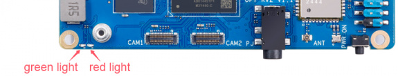
As long as the development board is powered on, the red LED light will be always on. This is controlled by hardware and cannot be turned off by software. The red LED light can be used to determine whether the power of the development board has been turned on normally.
The green LED light will keep flashing after the kernel starts, which is controlled by software.
The method of setting the green light on and off and flashing is as follows:
Note: The following operations must be performed as the root user.
First enter the Green Light settings directory.
root@orangepi:~# cd /sys/class/leds/sys-led
The command to set the green light to stop flashing is as follows:
root@orangepi:/sys/class/leds/sys-led# echo none > trigger
The command to set the green light to always be on is as follows:
root@orangepi:/sys/class/leds/sys-led# echo default-on > trigger
The command to set the green light to flash is as follows:
root@orangepi:/sys/class/leds/sys-led# echo heartbeat > trigger

Network connection test
Ethernet port test
The development board has two Gigabit Ethernet ports. The test methods for these two ports are the same. First, insert one end of the network cable into the Ethernet port of the development board, and connect the other end of the network cable to the router, and make sure the network is unobstructed.
After the system starts, the IP address will be automatically assigned to the Ethernet card through DHCP, and no other configuration is required.
The command to check the IP address in the Linux system of the development board is as follows:
orangepi@orangepi:~$ ip addr show
1: lo: <LOOPBACK,UP,LOWER_UP> mtu 65536 qdisc noqueue state UNKNOWN group default qlen 1000
link/loopback 00:00:00:00:00:00 brd 00:00:00:00:00:00
inet 127.0.0.1/8 scope host lo
valid_lft forever preferred_lft forever
inet6 ::1/128 scope host noprefixroute
valid_lft forever preferred_lft forever
2: end0: <BROADCAST,MULTICAST,UP,LOWER_UP> mtu 1500 qdisc fq_codel state UP group default qlen 1000
link/ether 00:e0:4c:68:00:13 brd ff:ff:ff:ff:ff:ff
inet 192.168.2.241/24 brd 192.168.2.255 scope global dynamic noprefixroute end0
valid_lft 43186sec preferred_lft 43186sec
inet6 fdcd:e671:36f4::47c/128 scope global dynamic noprefixroute
valid_lft 43186sec preferred_lft 43186sec
inet6 fdcd:e671:36f4:0:5689:f699:84ec:d4cb/64 scope global temporary dynamic
valid_lft 604786sec preferred_lft 85811sec
inet6 fdcd:e671:36f4:0:52ab:6ce7:cfc7:9ecf/64 scope global mngtmpaddr noprefixroute
valid_lft forever preferred_lft forever
inet6 fe80::f082:90bd:3fbd:dc01/64 scope link noprefixroute
valid_lft forever preferred_lft forever
3: end1: <BROADCAST,MULTICAST,UP,LOWER_UP> mtu 1500 qdisc fq_codel state UP group default qlen 1000
link/ether 00:e0:4c:68:00:14 brd ff:ff:ff:ff:ff:ff
inet 192.168.2.242/24 brd 192.168.2.255 scope global dynamic noprefixroute end1
valid_lft 43179sec preferred_lft 43179sec
inet6 fdcd:e671:36f4::49e/128 scope global dynamic noprefixroute
valid_lft 43177sec preferred_lft 43177sec
inet6 fdcd:e671:36f4:0:da95:4c2f:806f:5617/64 scope global temporary dynamic
valid_lft 604777sec preferred_lft 85899sec
inet6 fdcd:e671:36f4:0:7d9:7510:ccc5:fac9/64 scope global mngtmpaddr noprefixroute
valid_lft forever preferred_lft forever
inet6 fe80::db62:da89:a277:2ff0/64 scope link noprefixroute
valid_lft forever preferred_lft forever
4: wlan0: <NO-CARRIER,BROADCAST,MULTICAST,UP,LOWER_UP> mtu 1500 qdisc fq_codel state DORMANT group default
qlen 1000
link/ether 9c:b8:b4:38:c7:62 brd ff:ff:ff:ff:ff:ff
When using ifconfig to check the IP address, if the following message is displayed, it is because sudo is not added. The correct command is: sudo ifconfig.
orangepi@orangepi:~$ ifconfig
Command 'ifconfig' is available in the following places
* /sbin/ifconfig
* /usr/sbin/ifconfig
The command could not be located because '/sbin:/usr/sbin' is not included in the PATH environment variable.
This is most likely caused by the lack of administrative privileges associated with your user account.
ifconfig: command not found
There are three ways to check the IP address after the development board is started:
- Connect an HDMI display, then log in to the system and use the ip addr show command to view the IP address.
- Enter the ip addr show command in the debugging serial port terminal to view the IP address.
- 3. If there is no debugging serial port and no HDMI display, you can also view the IP address of the development board's network port through the router's management interface. However, this method often fails to see the IP address of the development board. If you cannot see it, the debugging method is as follows:
First check whether the Linux system has started normally. If the three-color light on the development board is flashing, it is generally started normally. If only the red light is on, it means that the system has not started normally.
Check whether the network cable is plugged in tightly, or try another cable;
Try another router (I have encountered many router problems, such as the router cannot assign IP addresses normally, or the IP addresses have been assigned normally but cannot be seen in the router);
If there is no router to replace, you can only connect an HDMI monitor or use the debug serial port to view the IP address.
It should also be noted that the development board DHCP automatically assigns IP addresses without any settings.
The command to test network connectivity is as follows. The ping command can be interrupted by pressing the Ctrl+C shortcut key.
orangepi@orangepi:~$ ping www.baidu.com -I end0 #Test command for one of the network ports
orangepi@orangepi:~$ ping www.baidu.com -I end1 #Test command for another network port
PING www.a.shifen.com (183.2.172.42) from 192.168.2.241 end0: 56(84) bytes of data.
64 bytes from 183.2.172.42: icmp_seq=1 ttl=53 time=10.1 ms
64 bytes from 183.2.172.42: icmp_seq=2 ttl=53 time=10.0 ms
64 bytes from 183.2.172.42: icmp_seq=3 ttl=53 time=9.91 ms
^C
--- www.a.shifen.com ping statistics ---
3 packets transmitted, 3 received, 0% packet loss, time 2002ms
rtt min/avg/max/mdev = 9.910/10.017/10.126/0.088 ms
WIFI connection test
Please do not connect to WIFI by modifying the /etc/network/interfaces configuration file. This method may cause problems when connecting to the WIFI network.
Server version image connects to WIFI through command
When the development board is not connected to Ethernet, not connected to HDMI display, and only connected to the serial port, it is recommended to use the command demonstrated in this section to connect to the WIFI network. Because nmtui can only display characters in some serial port software (such as minicom), it cannot display the graphical interface normally. Of course, if the development board is connected to Ethernet or HDMI display, you can also use the command demonstrated in this section to connect to the WIFI network.
- Log in to the Linux system first. There are three ways:
If the development board is connected to the network cable, you can log in to the Linux system remotely through SSH.
If the development board is connected to the debug serial port, you can use the serial terminal to log in to the Linux system.
If the development board is connected to the HDMI display, you can log in to the Linux system through the HDMI display terminal.
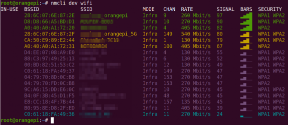
First use the nmcli dev wificommand to scan the surrounding WIFI hotspots.
orangepi@orangepi:~$ nmcli dev wifi
Then use the nmclicommand to connect to the scanned WIFI hotspot, where:
wifi_name needs to be replaced with the name of the WIFI hotspot you want to connect to.
wifi_passwd needs to be replaced with the password of the WIFI hotspot you want to connect to.
orangepi@orangepi:~$ sudo nmcli dev wifi connect wifi_name password wifi_passwd
Device 'wlan0' successfully activated with 'cf937f88-ca1e-4411-bb50-61f402eef293'.
Use the ip addr show wlan0 command to view the IP address of the wifi.
orangepi@orangepi:~$ ip addr show wlan0
11: wlan0: <BROADCAST,MULTICAST,UP,LOWER_UP> mtu 1500 qdisc pfifo_fast state UP group default qlen 1000
link/ether 23:8c:d6:ae:76:bb brd ff:ff:ff:ff:ff:ff
inet 192.168.1.11/24 brd 192.168.1.255 scope global dynamic noprefixroute wlan0
valid_lft 259192sec preferred_lft 259192sec
inet6 240e:3b7:3240:c3a0:c401:a445:5002:ccdd/64 scope global dynamic noprefixroute
valid_lft 259192sec preferred_lft 172792sec
inet6 fe80::42f1:6019:a80e:4c31/64 scope link noprefixroute
valid_lft forever preferred_lft forever
Use the ping command to test the connectivity of the WiFi network. The ping command can be interrupted by pressing the Ctrl+Cshortcut key.
orangepi@orangepi:~$ ping www.orangepi.online -I wlan0
PING www.orangepi.online (182.92.236.130) from 192.168.1.49 wlan0: 56(84) bytes of data.
64 bytes from 182.92.236.130 (182.92.236.130): icmp_seq=1 ttl=52 time=43.5 ms
64 bytes from 182.92.236.130 (182.92.236.130): icmp_seq=2 ttl=52 time=41.3 ms
64 bytes from 182.92.236.130 (182.92.236.130): icmp_seq=3 ttl=52 time=44.9 ms
64 bytes from 182.92.236.130 (182.92.236.130): icmp_seq=4 ttl=52 time=45.6 ms
64 bytes from 182.92.236.130 (182.92.236.130): icmp_seq=5 ttl=52 time=48.8 ms
^C
--- www.orangepi.online ping statistics ---
5 packets transmitted, 5 received, 0% packet loss, time 4006ms
rtt min/avg/max/mdev = 41.321/44.864/48.834/2.484 ms

The server version image connects to WIFI through a graphical method
- Log in to the Linux system first. There are three ways:
If the development board is connected to the network cable, you can log in to the Linux system remotely through SSH.
If the development board is connected to the debug serial port, you can use the serial terminal to log in to the Linux system (use MobaXterm as the serial software, and minicom cannot display the graphical interface).
If the development board is connected to an HDMI display, you can log in to the Linux system through the HDMI display terminal.
Then enter the nmtui command in the command line to open the wifi connection interface.
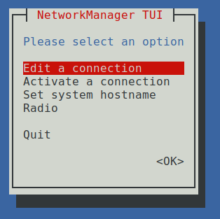
orangepi@orangepi:~$ sudo nmtui
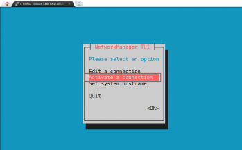
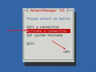
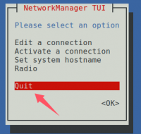
Enter the nmtui command to open the interface as shown below:
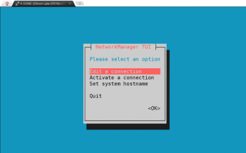
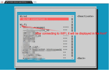
Select Activate a connect and press Enter.
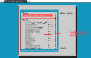
Then you can see all the searched WIFI hotspots.
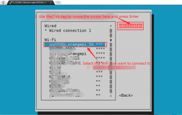
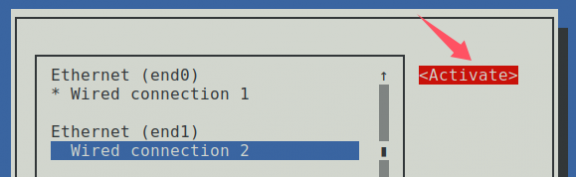
Select the WIFI hotspot you want to connect to, then use the Tab key to position the cursor at Activate and press Enter.
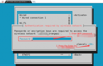
Then a dialog box for entering a password will pop up. Enter the corresponding password in Password and press Enter to start connecting to WIFI.
After the WIFI connection is successful, a "*" will be displayed in front of the connected WIFI name
You can view the IP address of the wifi network through the ip addr show wlan0 command.
orangepi@orangepi:~$ ip addr show wlan0
3: wlan0: <BROADCAST,MULTICAST,UP,LOWER_UP> mtu 1500 qdisc pfifo_fast state UP group default qlen 1000
link/ether 24:8c:d3:aa:76:bb brd ff:ff:ff:ff:ff:ff
inet 192.168.1.11/24 brd 192.168.1.255 scope global dynamic noprefixroute wlan0
valid_lft 259069sec preferred_lft 259069sec
inet6 240e:3b7:3240:c4a0:c401:a445:5002:ccdd/64 scope global dynamic noprefixroute
valid_lft 259071sec preferred_lft 172671sec
inet6 fe80::42f1:6019:a80e:4c31/64 scope link noprefixroute
valid_lft forever preferred_lft forever
Use the ping command to test the connectivity of the WiFi network. The ping command can be interrupted by pressing the Ctrl+C shortcut key.
orangepi@orangepi:~$ ping www.orangepi.online -I wlan0
PING www.orangepi.online (182.92.236.130) from 192.168.1.49 wlan0: 56(84) bytes of data.
64 bytes from 182.92.236.130 (182.92.236.130): icmp_seq=1 ttl=52 time=43.5 ms
64 bytes from 182.92.236.130 (182.92.236.130): icmp_seq=2 ttl=52 time=41.3 ms
64 bytes from 182.92.236.130 (182.92.236.130): icmp_seq=3 ttl=52 time=44.9 ms
64 bytes from 182.92.236.130 (182.92.236.130): icmp_seq=4 ttl=52 time=45.6 ms
64 bytes from 182.92.236.130 (182.92.236.130): icmp_seq=5 ttl=52 time=48.8 ms
^C
--- www.orangepi.online ping statistics ---
5 packets transmitted, 5 received, 0% packet loss, time 4006ms
rtt min/avg/max/mdev = 41.321/44.864/48.834/2.484 ms


Testing methods for desktop images
First, click on the upper right corner of the desktop (please do not connect the network cable when testing WIFI).

Then click the Settings icon in the drop-down box that pops up.

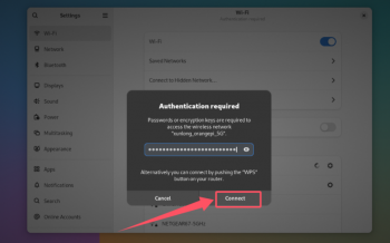
Then you can see the searched WIFI hotspots under Visible Networks in the settings interface, and then click the WIFI hotspot you want to connect to.

Then enter the password of the WIFI hotspot and click Connect to start connecting to WIFI.
After connecting to WIFI, you can open the browser to check whether you can access the Internet. The browser entrance is shown in the figure below:
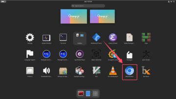
If you can open other web pages after opening the browser, it means the WIFI connection is normal.


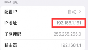
How to set a static IP address
Please do not set a static IP address by modifying the /etc/network/interfaces configuration file.
Using nmtui command to set static IP address
First run the nmtuicommand.
orangepi@orangepi:~$ sudo nmtui
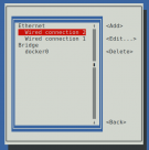
Then select Edit a connection and press Enter.
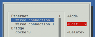
Then select the network interface for which you want to set a static IP address. For example, to set a static IP address for an Ethernet interface, select Wired connection 1 or Wired connection 2.
Then select Edit using the Tab key and press Enter.
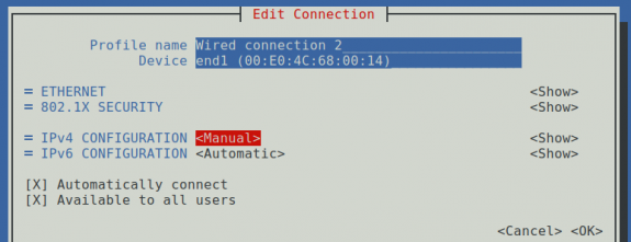
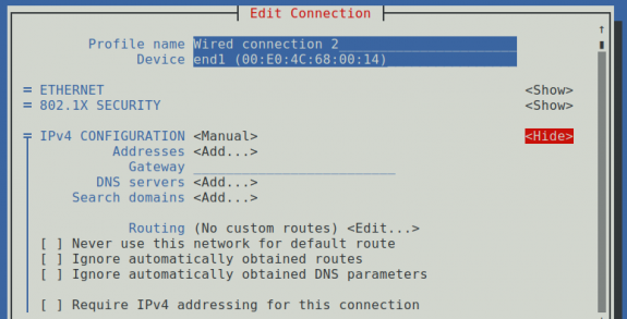
Then use the Tab key to move the cursor to the <Automatic> position shown in the figure below to configure IPv4.


- Press Enter, use the up and down arrow keys to select Manual, and then press Enter to confirm.

The display after selection is as shown below:
Then use the Tab key to move the cursor to <Show>.
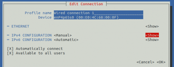
Then press Enter, and the following setting interface will pop up.
Then you can set the IP address (Addresses), gateway (Gateway) and DNS server address as shown in the figure below (there are many other setting options, please explore them yourself). Please set them according to your specific needs. The value set in the figure below is just an example.
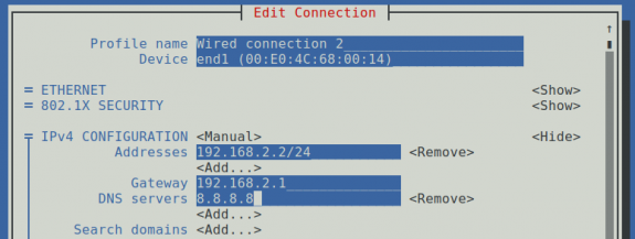
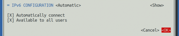
After setting, move the cursor to <OK> in the lower right corner and press Enter to confirm.
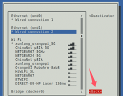
Then click <Back>to return to the previous selection interface.
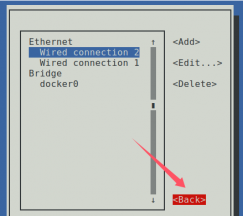
Then select Activate a connection, move the cursor to <OK>, and press Enter.
Then select the network interface you want to configure, such as Wired connection 2, move the cursor to <Deactivate>, and press Enter to disable Wired connection 2.
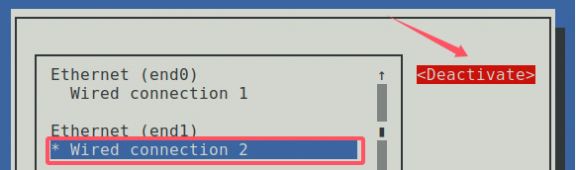
Then please do not move the cursor and press the Enter key to re-enable Wired connection 2, so that the static IP address set previously will take effect.
Then you can exit nmtui using the <Back> and Quit buttons.
Then use p addr show end1 to see that the IP address of the network port has become the static IP address set previously.
orangepi@orangepi:~$ ip addr show end1
3: end1: <BROADCAST,MULTICAST,UP,LOWER_UP> mtu 1500 qdisc fq_codel state UP group default qlen 1000
link/ether 00:e0:4c:68:00:14 brd ff:ff:ff:ff:ff:ff
inet 192.168.2.2/24 brd 192.168.2.255 scope global noprefixroute end1
valid_lft forever preferred_lft forever
inet6 fdcd:e671:36f4::49e/128 scope global dynamic noprefixroute
valid_lft 42950sec preferred_lft 42950sec
inet6 fdcd:e671:36f4:0:2139:e484:d595:deda/64 scope global temporary dynamic
valid_lft 604550sec preferred_lft 85735sec
inet6 fdcd:e671:36f4:0:7d9:7510:ccc5:fac9/64 scope global mngtmpaddr noprefixroute
valid_lft forever preferred_lft forever
inet6 fe80::db62:da89:a277:2ff0/64 scope link noprefixroute
valid_lft forever preferred_lft forever
Then you can test the network connectivity to check whether the IP address is configured OK. The ping command can be interrupted by pressing the Ctrl+C shortcut key.
orangepi@orangepi:~$ ping www.baidu.com -I end1
PING www.a.shifen.com (183.2.172.42) from 192.168.2.2 end1: 56(84) bytes of data.
64 bytes from 183.2.172.42: icmp_seq=1 ttl=53 time=10.2 ms
64 bytes from 183.2.172.42: icmp_seq=2 ttl=53 time=9.89 ms
64 bytes from 183.2.172.42: icmp_seq=3 ttl=53 time=9.64 ms
^C
--- www.a.shifen.com ping statistics ---
3 packets transmitted, 3 received, 0% packet loss, time 2003ms
rtt min/avg/max/mdev = 9.640/9.915/10.219/0.237 ms


How to create a WIFI hotspot through create_ap
create_ap is a script that helps quickly create a WIFI hotspot on Linux. It supports bridge and NAT modes and can automatically combine hostapd, dnsmasq and iptables to complete the setting of WIFI hotspot, avoiding users from making complex configurations. The github address is as follows:
https://github.com/oblique/create_ap
If you are using the latest image, the create_ap script is pre-installed. You can use the create_ap command to create a WIFI hotspot. The basic command format of create_ap is as follows:
create_ap [options] <wifi-interface> [<interface-with-internet>] [<access-point-name> [<passphrase>]]
* options:This parameter can be used to specify the encryption method, the frequency band of the WIFI hotspot, the bandwidth mode, the network sharing method, etc. You can get the options through create_ap -h
* wifi-interface:The name of the wireless network card
* interface-with-internet:The name of the network card that can connect to the Internet, usually eth0
* access-point-name:Hotspot Name
* passphrase:Hotspot password
create_ap method to create a WIFI hotspot in NAT mode
- Enter the following command to create a WiFi hotspot in NAT mode with the name orangepi and the password orangepi.
orangepi@orangepi:~$ sudo create_ap -m nat wlan0 end0 orangepi orangepi
If the following information is output, it means that the WIFI hotspot is created successfully.
orangepi@orangepi:~$ sudo create_ap -m nat wlan0 end0 orangepi orangepi
Config dir: /tmp/create_ap.wlan0.conf.Ks6HobEw
PID: 5405
Network Manager found, set ap0 as unmanaged device... DONE
Creating a virtual WiFi interface... ap0 created.
Sharing Internet using method: nat
hostapd command-line interface: hostapd_cli -p /tmp/create_ap.wlan0.conf.Ks6HobEw/hostapd_ctrl
ap0: interface state UNINITIALIZED->ENABLED
ap0: AP-ENABLED
Now take out your mobile phone and find the WIFI hotspot named orangepi created by the development board in the searched WIFI list. Then you can click orangepi to connect to the hotspot. The password is the orangepiset above.
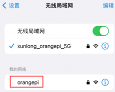
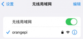
The display after successful connection is as shown below:

In NAT mode, the wireless device connected to the development board's hotspot requests an IP address from the development board's DHCP service, so there will be two different network segments. For example, the IP of the development board here is 192.168.1.X.
orangepi@orangepi:~$ ifconfig end0
end0: flags=4163<UP,BROADCAST,RUNNING,MULTICAST> mtu 1500
inet 192.168.1.241 netmask 255.255.255.0 broadcast 192.168.2.255
inet6 fdcd:e671:36f4:0:abd1:3c87:332a:dd20 prefixlen 64 scopeid 0x0<global>
inet6 fdcd:e671:36f4:0:52ab:6ce7:cfc7:9ecf prefixlen 64 scopeid 0x0<global>
inet6 fe80::f082:90bd:3fbd:dc01 prefixlen 64 scopeid 0x20<link>
inet6 fdcd:e671:36f4::47c prefixlen 128 scopeid 0x0<global>
ether 00:e0:4c:68:00:13 txqueuelen 1000 (Ethernet)
RX packets 17817 bytes 22181411 (22.1 MB)
RX errors 0 dropped 0 overruns 0 frame 0
TX packets 13179 bytes 2475256 (2.4 MB)
TX errors 0 dropped 0 overruns 0 carrier 0 collisions 0
device interrupt 78 base 0xd000
device interrupt 83
The DHCP service of the development board will assign an IP address of 192.168.12.0/24 to the device connected to the hotspot by default. At this time, click the connected WIFI hotspot orangepi, and then you can see that the IP address of the mobile phone is 192.168.12.X.


If you want to specify a different network segment for the connected device, you can specify it through the -g parameter, such as using the -g parameter to specify the network segment of the access point AP as 192.168.2.1.
orangepi@orangepi:~$ sudo create_ap -m nat wlan0 enP3p49s0 orangepi orangepi -g 192.168.2.1


At this time, after connecting to the hotspot through the mobile phone, click the connected WIFI hotspot orangepi, and then you can see that the IP address of the mobile phone is 192.168.2.X.


- If you do not specify the --freq-band parameter, the default hotspot created is the 2.4G band. If you want to create a 5G band hotspot, you can specify it with the --freq-band 5 parameter. The specific command is as follows:
orangepi@orangepi:~$ sudo create_ap -m nat wlan0 end0 orangepi orangepi --freq-band 5
- If you need to hide the SSID, you can specify the --hidden parameter. The specific command is as follows:
orangepi@orangepi:~$ sudo create_ap -m nat wlan0 end0 orangepi orangepi --hidden
At this time, the mobile phone cannot search for the WIFI hotspot. You need to manually specify the WIFI hotspot name and enter the password to connect to the WIFI hotspot.

create_ap method to create a WIFI hotspot in bridge mode
- Enter the following command to create a WiFi hotspot in bridge mode with the name orangepi and the password orangepi.
orangepi@orangepi:~$ sudo create_ap -m bridge wlan0 end0 orangepi orangepi
If the following information is output, it means that the WIFI hotspot is created successfully.
orangepi@orangepi:~$ sudo create_ap -m bridge wlan0 end0 orangepi orangepi
[sudo] password for orangepi:
Config dir: /tmp/create_ap.wlan0.conf.fg9U5Xgt
PID: 3141
Network Manager found, set ap0 as unmanaged device... DONE
Creating a virtual WiFi interface... ap0 created.
Sharing Internet using method: bridge
Create a bridge interface... br0 created.
hostapd command-line interface: hostapd_cli -p /tmp/create_ap.wlan0.conf.fg9U5Xgt/hostapd_ctrl
ap0: interface state UNINITIALIZED->ENABLED
ap0: AP-ENABLED
Now take out your mobile phone and find the WIFI hotspot named orangepi created by the development board in the searched WIFI list. Then you can click orangepi to connect to the hotspot. The password is the orangepi set above.
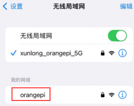
The display after successful connection is as shown below:
In bridge mode, the wireless device connected to the development board's hotspot also requests an IP address from the DHCP service of the main router (the router to which the development board is connected). For example, the IP of the development board here is 192.168.1.X.
orangepi@orangepi:~$ ifconfig end0
end0: flags=4163<UP,BROADCAST,RUNNING,MULTICAST> mtu 1500
inet 192.168.1.150 netmask 255.255.255.0 broadcast 192.168.1.255
inet6 fe80::938f:8776:5783:afa2 prefixlen 64 scopeid 0x20<link>
ether 4a:a0:c8:25:42:82 txqueuelen 1000 (Ethernet)
RX packets 25370 bytes 2709590 (2.7 MB)
RX errors 0 dropped 50 overruns 0 frame 0
TX packets 3798 bytes 1519493 (1.5 MB)
TX errors 0 dropped 0 overruns 0 carrier 0 collisions 0
device interrupt 83
The IP address of the device connected to the WIFI hotspot is also assigned by the main router, so the mobile phone and development board connected to the WIFI hotspot are in the same network segment. At this time, click the connected WIFI hotspot orangepi, and then you can see that the IP address of the mobile phone is also 192.168.1.X.

If you do not specify the --freq-band parameter, the default hotspot created is the 2.4G band. If you want to create a 5G band hotspot, you can specify it with the --freq-band 5 parameter. The specific command is as follows:

orangepi@orangepi:~$ sudo create_ap -m bridge wlan0 end0 orangepi orangepi --freq-band 5
- If you need to hide the SSID, you can specify the --hidden parameter. The specific command is as follows:
orangepi@orangepi:~$ sudo create_ap -m bridge wlan0 end0 orangepi orangepi --hidden
At this time, the mobile phone cannot search for the WIFI hotspot. You need to manually specify the WIFI hotspot name and enter the password to connect to the WIFI hotspot.
SSH remote login development board
By default, Linux systems enable SSH remote login and allow the root user to log in. Before logging in through SSH, you must first ensure that the Ethernet or WiFi network is connected, and then use the ip addr command or check the router to obtain the IP address of the development board.
SSH remote login to the development board under Ubuntu
- Get the IP address of the development board.
- Then you can remotely log in to the Linux system through the ssh command.
test@test:~$ ssh [email protected].xxx #Need to replace with the IP address of the development board
[email protected]'s password: #Enter the password here, the default password is orangepi
content of the password you entered. Please do not think that there is any malfunction. Just press Enter after entering it.
If the prompt refuses to connect, as long as you are using the image provided by Orange Pi, please do not doubt whether the password orangepi is wrong, but look for other reasons.
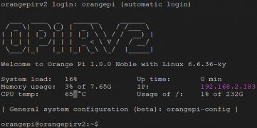
After successfully logging into the system, the display is as shown below:

If ssh cannot log in to the Linux system normally, first check whether the IP address of the development board can be pinged. If the ping is successful, you can log in to the Linux system through the serial port or HDMI display and then enter the following command on the development board to try to connect:

root@orangepi:~# reset_ssh.sh
If it still doesn't work, please re-burn the system and try again.
SSH remote login development board under Windows
- First, obtain the IP address of the development board.
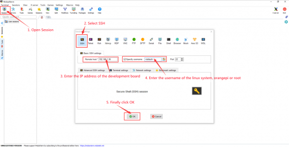
- Under Windows, you can use MobaXterm to remotely log in to the development board. First, create a new ssh session.
Open Session.
Select SSH in Session Setting.
Enter the IP address of the development board in Remote host.
Enter the Linux user name root or orangepi in Specify username.
Click OK.

You will then be prompted to enter a password. The default password for both root and orangepi users is orangepi.
Please note that when you enter the password, the specific content of the password will not be displayed on the screen. Please do not think that there is any malfunction. Just press Enter after entering it.

- After successfully logging into the system, the display is as shown below:

How to upload files to the Linux system of the development board
How to upload files from Ubuntu PC to the Linux system of the development board
How to upload files using the scp command
Use the scp command to upload files from the Ubuntu PC to the Linux system of the development board. The specific commands are as follows:
file_path:Need to be replaced with the path to the file to be uploaded.
orangepi:This is the user name of the Linux system of the development board. It can also be replaced with other names, such as root.
192.168.xx.xx: It is the IP address of the development board. Please modify it according to the actual situation.
/home/orangepi: The path in the Linux system of the development board can also be modified to other paths.
test@test:~$ scp file_path [email protected]:/home/orangepi/
If you want to upload a folder, you need to add the -r parameter.
test@test:~$ scp -r dir_path [email protected]:/home/orangepi/
There are more uses for scp. Please use the following command to view the man manual.
test@test:~$ man scp
How to upload files using FileZilla
First install filezilla in your Ubuntu PC.
test@test:~$ sudo apt install -y filezilla
Then open filezilla using the command below.
test@test:~$ filezilla
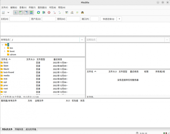
The interface after opening filezilla is as shown below. At this time, the remote site on the right is empty.
The method of connecting the development board is shown in the figure below:


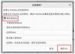
Then select Save Password and click OK.
Then select Always trust this host and click OK.


- After the connection is successful, you can see the directory structure of the development board's Linux file system on the right side of the filezilla software.

- Then select the path to be uploaded to the development board on the right side of the filezilla software, select the file to be uploaded in the Ubuntu PC on the left side of the filezilla software, right-click the mouse, and then click the upload option to start uploading the file to the development board.

After uploading is complete, you can go to the corresponding path in the Linux system of the development board to view the uploaded files.
The method for uploading a folder is the same as that for uploading a file, so I will not go into details here.
How to upload files from Windows PC to the Linux system of the development board
How to upload files using FileZilla
- First download the installation file of the Windows version of the filezilla software. The download link is as follows:
https://filezilla-project.org/download.php?type=client

The downloaded installation package is as shown below, then double-click to install directly.
FileZilla_Server_1.5.1_win64-setup.exe
During the installation process, select Decline on the following installation interface, and then select Next>.

- The interface after opening filezilla is as shown below. At this time, the remote site on the right is empty.

- The method of connecting the development board is shown in the figure below:
- Then select Save Password and click OK.

- Then select Always trust this host and click OK.

- After the connection is successful, you can see the directory structure of the development board's Linux file system on the right side of the filezilla software.

- Then select the path to be uploaded to the development board on the right side of the filezilla software, then select the file to be uploaded in the Windows PC on the left side of the filezilla software, right-click the mouse, and then click the upload option to start uploading the file to the development board.

After uploading is complete, you can go to the corresponding path in the Linux system of the development board to view the uploaded files.
The method for uploading a folder is the same as that for uploading a file, so I will not go into details here.
HDMI test
HDMI Display Test
Use an HDMI to HDMI cable to connect the Orange Pi development board and the HDMI display.
After starting the Linux system, if the HDMI monitor has image output, it means that the HDMI interface is working properly.
Please note that although many laptops are equipped with HDMI interfaces, the HDMI interfaces of laptops generally only have output functions and do not have HDMI in functions, which means that the HDMI output of other devices cannot be displayed on the laptop screen.
When you want to connect the HDMI of the development board to the HDMI port of a laptop, please make sure that your laptop supports the HDMI in function.
When there is no display on HDMI, please first check whether the HDMI cable is plugged in tightly. After confirming that the connection is OK, you can try a different screen to see if there is any display.
HDMI resolution setting method
First click the upper right corner of the desktop, then click the settings icon to open the settings interface.
Then find Display in the settings interface to see the current resolution of the system.
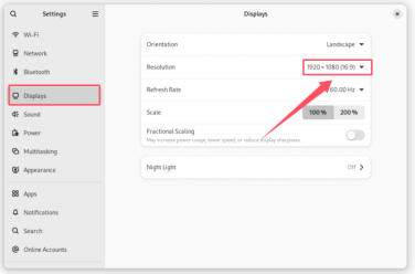
Click the drop-down box of Resolution to see all the resolutions currently supported by the monitor.
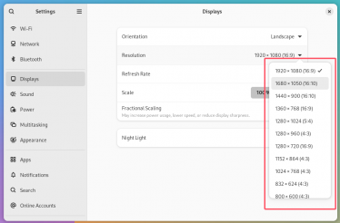
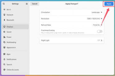
Then select the resolution you want to set and click Apply.
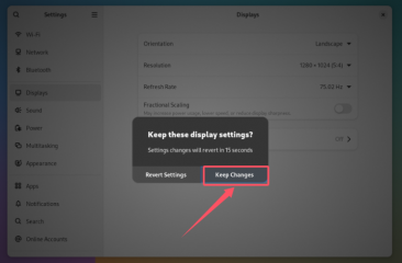
After the new resolution is set, select Keep Changes.


How to use Bluetooth
Desktop image testing method
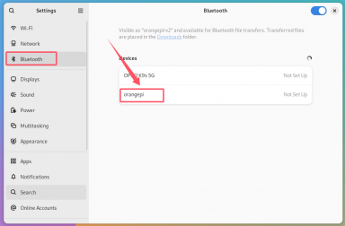
First click the upper right corner of the desktop, then click the settings icon to open the settings interface.
Then find Bluetooth in the settings interface. Under Devices, the Bluetooth devices scanned around will be displayed. Then select the Bluetooth device you want to connect to start pairing.
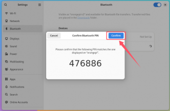
After pairing starts, a pairing confirmation box will pop up. Select Confirm. Confirmation is also required on the phone.


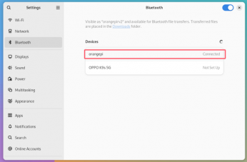
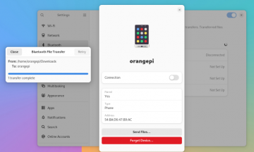
After pairing with the phone, you can click on the paired Bluetooth device and select Send a File to start sending a picture to the phone.
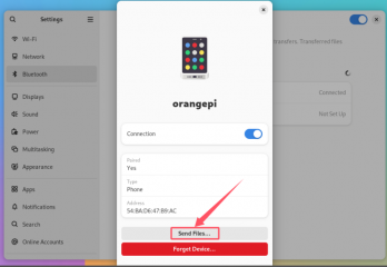
The interface for sending pictures is as follows:


USB interface test
The USB port can be connected to a USB hub to expand the number of USB ports.
Connect a USB mouse or keyboard to test
- Plug the USB keyboard into the USB port of the Orange Pi development board.
- Connecting Orange Pi to HDMI display
- If the mouse or keyboard can operate the system normally, it means that the USB interface is working properly (the mouse can only be used in the desktop version of the system)
Test by connecting USB storage device
- First, insert the USB flash drive or USB mobile hard disk into the USB port of the Orange Pi development board.
- Execute the following command. If you can see the output of sdX, it means the USB disk has been successfully recognized.
orangepi@orangepi:~$ cat /proc/partitions | grep "sd*"
major minor #blocks name
8 0 30044160 sda
8 1 30043119 sda1
- Use the mount command to mount the USB drive to /mnt, and then you can view the files in the USB drive.
orangepi@orangepi:~$ sudo mount /dev/sda1 /mnt/
orangepi@orangepi:~$ ls /mnt/
test.txt
- After mounting, you can use the df -h command to view the capacity usage and mount point of the USB drive.
orangepi@orangepi:~$ df -h | grep "sd"
/dev/sda1 29G 208K 29G 1% /mnt
USB camera test
First, you need to prepare a USB camera that supports UVC protocol as shown in the figure below or similar, and then insert the USB camera into the USB port of the Orange Pi development board.

Through the v4l2-ctl command, you can see that the device node information of the USB camera is /dev/video20
orangepi@orangepi:~$ v4l2-ctl --list-devices | grep -A 3 "Q8 HD Webcam"
Q8 HD Webcam: Q8 HD Webcam (usb-fc880000.usb-1):
/dev/video20
/dev/video21
/dev/media1
Note that the l in v4l2 is a lowercase letter l, not the number 1.
In addition, the serial number of the video is not always video20, please refer to the actual one you see.
How to use fswebcam to test USB camera
Install fswebcam
orangepi@orangepi:~$ sudo apt update
orangepi@orangepi:~$ sudo apt-get install -y fswebcam
After installing fswebcam, you can use the following command to take pictures
-d Option to specify the device node of the USB camera
--no-banner is used to remove the watermark of the photo
The -r option is used to specify the resolution of the photo
The -S option is used to set the number of previous frames to skip
./image.jpg is used to set the name and path of the generated photo
orangepi@orangepi:~$ sudo fswebcam -d /dev/video0 \
--no-banner -r 1280x720 -S 5 ./image.jpg
In the server version of Linux, after taking the photo, you can use the scp command to transfer the photo to the Ubuntu PC for mirror viewing.
orangepi@orangepi:~$ scp image.jpg [email protected]:/home/test (Modify the IP address and path according to the actual situation)
In the desktop version of Linux system, you can directly view the captured pictures through the HDMI display
Audio Test
Testing Audio Methods on Desktop Systems
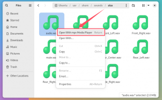
First open the file manager.

Then find the file below (if there is no audio file in the system, you can upload an audio file to the system yourself).

Then select the audio.wav file, right-click and choose to open with mpv to start playing.
A method for switching between different audio devices such as HDMI playback and headphone playback.
First click on the upper right corner, then click on the settings icon to open the settings interface.


Then find the Sound settings.
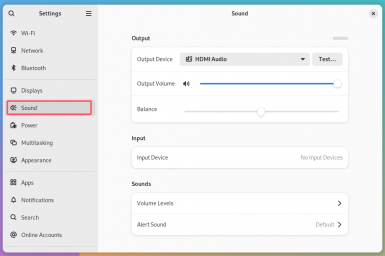
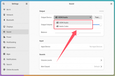
Then select the audio device you want to play in the drop-down selection box of Output Device (select Audio Codec to output the sound from the headphones, select HDMI Audio to output the sound from HDMI)


How to play audio using commands
Headphone jack audio playback test
First, plug the earphone into the earphone jack of the development board.
Then you can use the aplay -l command to view the sound card devices supported by the Linux system. From the output below, we can see that card 1 is the es8388 sound card device, which is the sound card device of the headset.
orangepi@orangepi:~$ aplay -l
**** List of PLAYBACK Hardware Devices ****
card 0: sndhdmi [snd-hdmi], device 0: SSPA2-dummy_codec dummy_codec-0 []
Subdevices: 1/1
Subdevice #0: subdevice #0
card 1: sndes8323 [snd-es8323], device 0: i2s-dai0-ES8323 HiFi ES8323 HiFi-0 []
Subdevices: 1/1
Subdevice #0: subdevice #0
Then use the aplay command to play the audio file that comes with the system. If the headphones can hear the sound, it means that the hardware can be used normally.
orangepi@orangepi:~$ aplay -D hw:1,0 /usr/share/sounds/alsa/audio.wav
Playing WAVE 'audio.wav' : Signed 16 bit Little Endian, Rate 44100 Hz, Stereo

HDMI audio playback test
First, use an HDMI to HDMI cable to connect the Orange Pi development board to the TV (other HDMI displays need to ensure that they can play audio)
Then check the HDMI sound card serial number. From the output below, we can know that the HDMI sound card is card 0
orangepi@orangepi:~$ aplay -l
**** List of PLAYBACK Hardware Devices ****
card 0: sndhdmi [snd-hdmi], device 0: SSPA2-dummy_codec dummy_codec-0 []
Subdevices: 1/1
Subdevice #0: subdevice #0
......
Then use the aplay command to play the audio file that comes with the system. If the HDMI display or TV can hear the sound, it means that the hardware can be used normally.
orangepi@orangepi:~$ aplay -D hw:0,0 /usr/share/sounds/alsa/audio.wav
How to test recording using commands
The Orange Pi RV2 development board does not have an onboard MIC, so you can only record audio through headphones with a MIC function. After plugging a headphone with a MIC function into the development board, run the following command to record an audio clip through the headphone:
orangepi@orangepi:~$ arecord -D hw:1,0 -d 5 -f cd -t wav /tmp/test.wav
Temperature sensor
- The command to view the system temperature sensor is:
orangepi@orangepi:~$ sensors
cluster0_thermal-virtual-0
Adapter: Virtual device
temp1: +59.0°C
cluster1_thermal-virtual-0
Adapter: Virtual device
temp1: +60.0°C
The command to check the current temperature of the nvme ssd solid state drive is:
orangepi@orangepi:~$ sudo smartctl -a /dev/nvme0 | grep "Temperature:"
Temperature: 40 Celsius
26 Pin Interface Pin Description
Please refer to the following figure for the order of the 26-pin interface pins of the Orange Pi RV2 development board
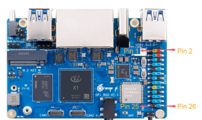
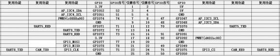
The functions of the 26 pin interface pins of the Orange Pi RV2 development board are shown in the following table
Below is the complete pin diagram of 26 pins
The table below is a picture of the left half of the complete table above, which can be seen more clearly.
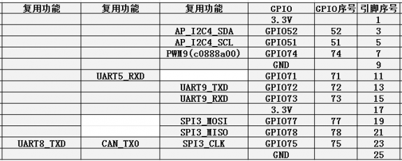
The table below is the right half of the complete table above, which can be seen more clearly
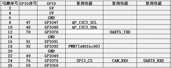
In the table above, the base addresses of the corresponding registers are marked for pwm, which is useful for checking which pwmchip in /sys/class/pwm/ corresponds to which pwm pin in the 26-pin header.
There are a total of 17 GPIO ports in the 26-pin interface, and the voltage of all GPIO ports is 3.3v


How to install wiringOP
Note that wiringOP is pre-installed in the Linux image released by Orange Pi. Unless the wiringOP code is updated, you do not need to download, compile and install it again. You can use it directly.
The storage path of the compiled wiringOP deb package in orangepi-build is:
orangepi-build/external/cache/debs/riscv64/wiringpi_x.xx.deb
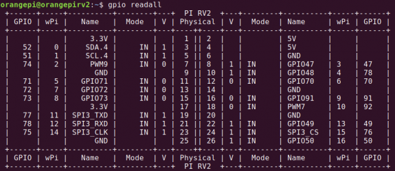
After entering the system, you can run the gpio readall command. If you can see the following output, it means wiringOP has been pre-installed and can be used normally.

Download the wiringOP code
orangepi@orangepi:~$ sudo apt update
orangepi@orangepi:~$ sudo apt install -y git
orangepi@orangepi:~$ git clone https://github.com/orangepi-xunlong/wiringOP.git -b next
Note that Orange Pi RV2 needs to download the wiringOP next branch code, please do not miss the -b next parameter.
If you have problems downloading the code from GitHub, you can directly use the wiringOP source code that comes with the Linux image, which is stored in: /usr/src/wiringOP.
Compile and install wiringOP
orangepi@orangepi:~$ cd wiringOP
orangepi@orangepi:~/wiringOP$ sudo ./build clean
orangepi@orangepi:~/wiringOP$ sudo ./build
Test the output of the gpio readall command as follows
26pin interface GPIO, I2C, UART, SPI, CAN and PWM test
26pin GPIO port test
The Linux system released by Orange Pi has a pre-installed blink_all_gpio program, which will set all 17 GPIO ports in the 26-pin to switch high and low levels continuously.
After running the blink_all_gpio program, when you use a multimeter to measure the voltage level of the GPIO port, you will find that the GPIO pin will switch between 0 and 3.3v. Using this program, we can test whether the GPIO port can work properly.
The way to run the blink_all_gpio program is as follows:
orangepi@orangepi:~$ sudo blink_all_gpio #Remember to add sudo permissions
[sudo] password for orangepi: #You need to enter your password here
There are 17 GPIO ports available in the 26-pin development board. The following example shows how to set the high and low levels of the GPIO port using pin 7, which corresponds to GPIO74 and wPi number 2.
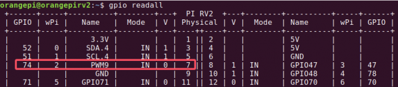
First set the GPIO port to output mode, where the third parameter needs to input the wPi number corresponding to the pin
root@orangepi:~/wiringOP# gpio mode 2 out
Then set the GPIO port to output a low level. After setting, you can use a multimeter to measure the voltage value of the pin. If it is 0v, it means that the low level is set successfully.
root@orangepi:~/wiringOP# gpio write 2 0
Using gpio readall, you can see that the value of pin 7 (V) has changed to 0
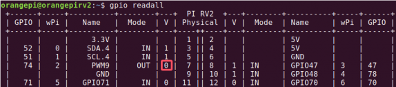
Then set the GPIO port to output a high level. After setting, you can use a multimeter to measure the voltage value of the pin. If it is 3.3v, it means that the high level is set successfully.
root@orangepi:~/wiringOP# gpio write 2 1
Using gpio readall, you can see that the value of pin 7 (V) has changed to 1
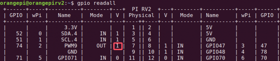
The setting method of other pins is similar. Just change the serial number of wPi to the serial number corresponding to the pin.


How to set pull-up and pull-down resistors on GPIO pins
Note that only the following 8 GPIO pins of Orange Pi RV2 can be set to pull up and down normally. Other GPIO pins do not support the function of setting pull-up and pull-down resistors.

Below, we take pin 8, which corresponds to GPIO 47 and wPi number 3, as an example to demonstrate how to set the pull-up and pull-down resistors of the GPIO port.
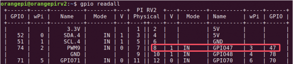
First, you need to set the GPIO port to input mode. The third parameter needs to enter the wPi number corresponding to the pin.
root@orangepi:~# gpio mode 3 in
After setting to input mode, execute the following command to set the GPIO port to pull-up mode
root@orangepi:~# gpio mode 3 up
Then enter the following command to read the level of the GPIO port. If the level is 1, it means that the pull-up mode is set successfully.
root@orangepi:~# gpio read 3
1
Then execute the following command to set the GPIO port to pull-down mode
root@orangepi:~# gpio mode 3 down
Then enter the following command to read the level of the GPIO port. If the level is 0, it means that the pull-down mode is set successfully.
root@orangepi:~# gpio read 3
0

26pin SPI test
As shown in the figure below, the available spi for Orange Pi RV2 is spi3
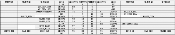
The corresponding pins of SPI3 in 26 pins are shown in the following table.

| SPI3 corresponds to 26pin | |
| MOSI | Pin 19 |
| MISO | Pin 21 |
| CLK | Pin 23 |
| CS0 | Pin 24 |
| Dtbo Configuration | spi3-cs0-spidev |
In Linux system, the SPI in 26 pins is closed by default and needs to be opened manually before use. The detailed steps are as follows:
First run orangepi-config. Ordinary users should remember to add sudo permissions.
orangepi@orangepi:~$ sudo orangepi-config
Then select System
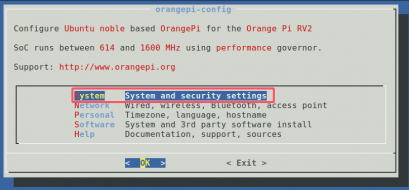
Then select Hardware
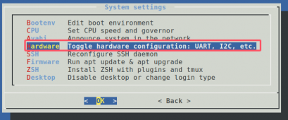
Then use the arrow keys on the keyboard to locate the position shown in the figure below, and then use the spacebar to select and open the SPI3 configuration

Then select <Save> to save
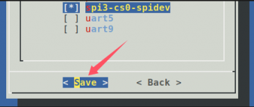
Then select <Back>

Then select <Reboot> to restart the system to make the configuration take effect.

After restarting, enter the system and check whether there is a device node of spidevx.x in the Linux system. If it exists, it means that SPI has been set up and can be used directly.
orangepi@orangepi:~$ ls /dev/spidev*
/dev/spidev3.0
Do not short the mosi and miso pins of SPI3. The output of running spidev_test is as follows. It can be seen that the data of TX and RX are inconsistent.
orangepi@orangepi:~$ sudo spidev_test -v -D /dev/spidev3.0
spi mode: 0x0
bits per word: 8
max speed: 500000 Hz (500 KHz)
TX | FF FF FF FF FF FF 40 00 00 00 00 95 FF FF FF FF FF FF FF FF FF FF FF FF FF FF FF FF FF FF F0 0D | ......@.…▒..................▒.
RX | FF FF FF FF FF FF FF FF FF FF FF FF FF FF FF FF FF FF FF FF FF FF FF FF FF FF FF FF FF FF FF FF | ............................….
Then short the mosi and miso pins of SPI3 and run spidev_test again. The output is as follows: you can see that the data sent and received are the same.
orangepi@orangepi:~$ sudo spidev_test -v -D /dev/spidev3.0
spi mode: 0x0
bits per word: 8
max speed: 500000 Hz (500 KHz)
TX | FF FF FF FF FF FF 40 00 00 00 00 95 FF FF FF FF FF FF FF FF FF FF FF FF FF FF FF FF FF FF F0 0D | ......@.…▒..................▒.
RX | FF FF FF FF FF FF 40 00 00 00 00 95 FF FF FF FF FF FF FF FF FF FF FF FF FF FF FF FF FF FF F0 0D | ......@.…▒..................▒.


26pin I2C test
As can be seen from the table below, the available i2c buses for Orange Pi RV2 are i2c3 and i2c4, a total of two i2c buses.
The corresponding pins of the two sets of I2C buses in 26 pins are shown in the following table.
| I2C bus | SDA corresponds to 26pin | SCL corresponds to 26pin | dtbo corresponding configuration |
| I2C3 | Pin 10 | Pin 8 | i2c3 |
| I2C4 | Pin 3 | Pin 5 | i2c4 |
In Linux system, the I2C bus in 26 pins is closed by default and needs to be opened manually before it can be used. The detailed steps are as follows:
First run orangepi-config. Ordinary users should remember to add sudo permissions.
orangepi@orangepi:~$ sudo orangepi-config
Then select System
Then select Hardware
Then use the arrow keys on the keyboard to locate the position shown in the figure below, and then use the spacebar to select the I2C configuration you want to open

Then select <Save> to save
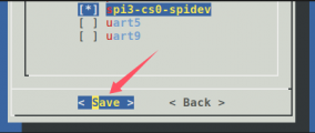
Then select <Back>
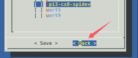
Then select <Reboot> to restart the system for the configuration to take effect.

After starting the Linux system, first confirm that there is a device node that needs to use I2C under /dev
orangepi@orangepi:~$ ls /dev/i2c-*
Then connect an i2c device to the i2c pin of the 26pin connector
Then use the i2cdetect -y command. If the address of the connected i2c device can be detected, it means that i2c can be used normally.
orangepi@orangepi:~$ sudo i2cdetect -y -r 3 #Command for i2c3
orangepi@orangepi:~$ sudo i2cdetect -y -r 4 #Command for i2c4
26pin UART test
As can be seen from the table below, the available uarts for Orange Pi RV2 are uart5, uart8 and uart9, a total of three uart buses.
The corresponding pins of the three groups of UART buses in 26 pins are shown in the following table.
| UART Bus | RX corresponds to 26pin | TX corresponds to 26pin | dtbo corresponding configuration |
| UART5 | Pin 11 | Pin 12 | uart5 |
| UART8 | Pin 24 | Pin 23 | uart8 |
| UART9 | Pin 13 | Pin 15 | uart9 |
In Linux system, the UART in 26 pins is closed by default and needs to be opened manually. The detailed steps are as follows:
First run orangepi-config. Ordinary users should remember to add sudo permissions.
orangepi@orangepi:~$ sudo orangepi-config
Then select System
Then select Hardware
Then use the arrow keys on the keyboard to locate the position shown in the figure below, and then use the spacebar to select the UART configuration you want to open

Then select <Save> to save

Then select <Back>

Then select <Reboot> to restart the system for the configuration to take effect.

After entering the Linux system, first confirm whether there is a device node corresponding to uart under /dev
orangepi@orangepi:~$ ls /dev/ttyS*
Then start testing the UART interface. First use the Dupont line to short-circuit the rx and tx of the UART interface to be tested.
Use the gpio serial command to test the loopback function of the serial port as shown below. If you can see the following print, it means that the serial port communication is normal (ttySX needs to be replaced with the corresponding uart node name, please do not copy it)
orangepi@orangepi:~$ sudo gpio serial /dev/ttySX
Out: 0: -> 0
Out: 1: -> 1
Out: 2: -> 2
Out: 3: -> 3
Out: 4: -> 4
Out: 5: -> 5^C
How to test PWM using /sys/class/pwm
As can be seen from the table below, Orange Pi RV2 has two PWM channels: pwm7 and pwm9.
The corresponding pins of PWM in 26 pins are shown in the following table.
| PWM Bus | Correspond 26pin | dtbo corresponding configuration |
| PWM7 | Pin 18 | pwm7 |
| PWM9 | Pin 7 | pwm9 |
In Linux system, PWM in 26 pins is disabled by default and needs to be enabled manually. The detailed steps are as follows:
First run orangepi-config. Ordinary users should remember to add sudo permissions.
orangepi@orangepi:~$ sudo orangepi-config
Then select System
Then selectHardware
Then use the arrow keys on the keyboard to locate the position shown in the figure below, and then use the spacebar to select the PWM configuration you want to turn on.

Then select <Save> to save
Then select <Back>
Then select <Reboot> to restart the system for the configuration to take effect
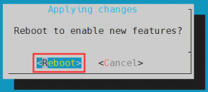
When a pwm is turned on, there will be an additional pwmchipX in /sys/class/pwm/ (X is a specific number). For example, after turning on pwm9, the pwmchipX under /sys/class/pwm/ will change from one to two.
orangepi@orangepi:~$ ls /sys/class/pwm/
pwmchip0 pwmchip1
Which pwmchip above corresponds to pwm9? Let's first check the output of the ls /sys/class/pwm/ -l command, as shown below:

Then from the table below, we can see that the base address of the pwm9 register is c0888a00. Looking at the output of the ls /sys/class/pwm/ -l command, we can see that pwmchip1 is linked to c0888a00.pwm, so the pwmchip corresponding to pwm9 is pwmchip1.
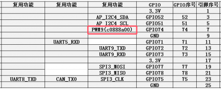
Then use the following command to make pwm9 output a 500Hz square wave (please switch to the root user first, then execute the following command)

root@orangepi:~# echo 0 > /sys/class/pwm/pwmchip1/export
root@orangepi:~# echo 200000 > /sys/class/pwm/pwmchip1/pwm0/period
root@orangepi:~# echo 100000 > /sys/class/pwm/pwmchip1/pwm0/duty_cycle
root@orangepi:~# echo 1 > /sys/class/pwm/pwmchip1/pwm0/enable
- The pwm9 test method demonstrated above is similar to other pwm test methods.
CAN test method
How to open CAN
As can be seen from the table below, the available CAN bus for Orange Pi RV2 is CAN0
In Linux system, the CAN in 26 pins is closed by default and needs to be opened manually before it can be used. The detailed steps are as follows:
First run orangepi-config. Ordinary users should remember to add sudo permissions.
orangepi@orangepi:~$ sudo orangepi-config
Then selectSystem
Then selectHardware
Then use the arrow keys on the keyboard to locate the position shown in the figure below, and then use the spacebar to select and open the configuration of can0

Then select <Save>
Then select <Back>
Then select <Reboot> to restart the system for the configuration to take effect

After entering the Linux system, use the sudo ifconfig -a command. If you can see the CAN device, it means that CAN has been correctly opened.
orangepi@orangepi:~$ sudo ifconfig -a
can0: flags=128<NOARP> mtu 16
unspec 00-00-00-00-00-00-00-00-00-00-00-00-00-00-00-00 txqueuelen 10 (UNSPEC)
RX packets 0 bytes 0 (0.0 B)
RX errors 0 dropped 0 overruns 0 frame 0
TX packets 0 bytes 0 (0.0 B)
TX errors 0 dropped 0 overruns 0 carrier 0 collisions 0
device interrupt 91
The pin corresponding to 26pin of CAN0 is
| CAN0 | |
| TX Pin | Corresponding to pin 23 |
| RX Pin | Corresponding to pin 24 |
Test sending and receiving messages using CANalyst-II analyzer
The CANalyst-II analyzer used in the test is shown in the figure below

CANalyst-II analyzer data download link
First, you need to install the USBCANToolSetup software

The shortcut after USBCANToolSetup is installed is:

You also need to install the USB driver
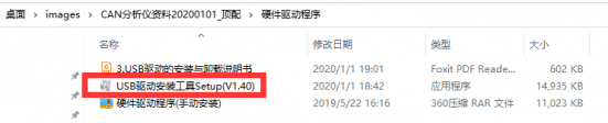
The USB port of CANalyst-II analyzer needs to be connected to the USB port of the computer.

To test the CAN function, you also need to prepare a CAN transceiver as shown in the figure below. The main function of the CAN transceiver is to convert the TTL signal of the CAN controller into the differential signal of the CAN bus.
The 3.3V pin of the CAN transceiver needs to be connected to the 3.3V pin of the 26pin of the development board
The GND pin of the CAN transceiver needs to be connected to the GND pin of the 26pin of the development board
The CAN TX pin of the CAN transceiver needs to be connected to the TX pin of the CAN bus in the 26-pin of the development board
The CAN RX pin of the CAN transceiver needs to be connected to the RX pin of the CAN bus in the 26-pin of the development board
The CANH pin of the CAN transceiver needs to be connected to the H interface of the analyzer
The CANL pin of the CAN transceiver needs to be connected to the L interface of the analyzer

Then you can open the USB-CAN software
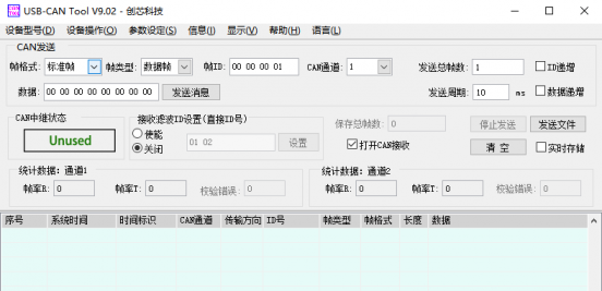
Then click Start Device
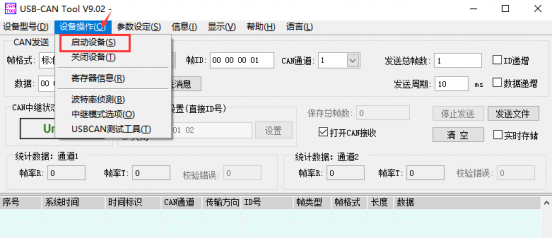
Then click OK
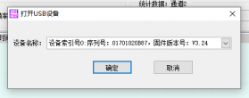
Set the baud rate to 1000k bps
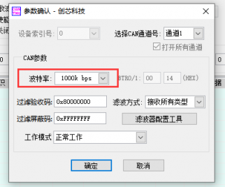
After successfully opening, the USB-CAN software will display the serial number and other information
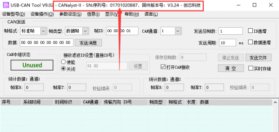
Development board receives CAN message test
First, set the baud rate of the CAN bus to 1000kbps in the Linux system of the development board
orangepi@orangepi:~$ sudo ip link set can0 down
orangepi@orangepi:~$ sudo ip link set can0 type can bitrate 1000000
orangepi@orangepi:~$ sudo ip link set can0 up
Then run the candump can0 command to prepare to receive messages.
orangepi@orangepi:~$ sudo candump can0
Then send a message to the development board in the USB-CAN software
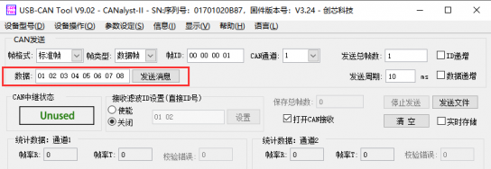
If the development board can receive the message sent by the analyzer, it means that the CAN bus can be used normally.
orangepi@orangepirv2:~$ sudo candump can0
can0 001 [8] 01 02 03 04 05 06 07 08
Development board sends CAN message test
First, set the CAN baud rate to 1000kbps in the Linux system
orangepi@orangepi:~$ sudo ip link set can0 down
orangepi@orangepi:~$ sudo ip link set can0 type can bitrate 1000000
orangepi@orangepi:~$ sudo ip link set can0 up
Execute the cansend command in the development board to send a message
orangepi@orangepi:~$ sudo cansend can0 123#1122334455667788
If the USB-CAN software can receive the message sent by the development board, it means the communication is successful
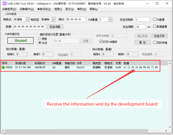


Installation and use of wiringOP-Python
wiringOP-Python is the Python version of wiringOP, which is used to operate the GPIO, I2C, SPI, UART and other hardware resources of the development board in Python programs.
Also note that some of the following commands are performed under the root user.
Installation of wiringOP-Python
First install the dependency package
root@orangepi:~# sudo apt-get update
root@orangepi:~# sudo apt-get -y install git swig python3-dev python3-setuptools
Then use the following command to download the source code of wiringOP-Python
Note that the following git clone--recursive command will automatically download the source code of wiringOP, because wiringOP-Python depends on wiringOP. Please make sure that there are no errors during the download process due to network problems.
If you have problems downloading the code from GitHub, you can directly use the wiringOP-Python source code that comes with the Linux image, which is stored in/usr/src/wiringOP-Python.
root@orangepi:~# git clone --recursive https://github.com/orangepi-xunlong/wiringOP-Python -b next
root@orangepi:~# cd wiringOP-Python
root@orangepi:~/wiringOP-Python# git submodule update --init --remote
Then use the following command to compile wiringOP-Python and install it into the Linux system of the development board
root@orangepi:~# cd wiringOP-Python
root@orangepi:~/wiringOP-Python# python3 generate-bindings.py > bindings.i
root@orangepi:~/wiringOP-Python# sudo python3 setup.py install
Then enter the following command. If help information is output, it means wiringOP-Python has been successfully installed. Press the q key to exit the help information interface.
root@orangepi:~/wiringOP-Python# python3 -c "import wiringpi; help(wiringpi)"
Help on module wiringpi:
NAME
wiringpi
DESCRIPTION
- This file was automatically generated by SWIG (http://www.swig.org).
- Version 4.0.2
- Do not make changes to this file unless you know what you are doing--modify
- the SWIG interface file instead.
The steps to test whether wiringOP-Python is successfully installed in the python command line are as follows:
- First use the python3 command to enter the python3 command line mode
root@orangepi:~# python3
- Then import the Python module of wiringPi
>>> import wiringpi;
- Finally, enter the following command to view the help information of wiringOP-Python. Press the q key to exit the help information interface.
>>> help(wiringpi)
Help on module wiringpi:
NAME
wiringpi
DESCRIPTION
- This file was automatically generated by SWIG (http://www.swig.org).
- Version 4.0.2
- Do not make changes to this file unless you know what you are doing--modify
- the SWIG interface file instead.
CLASSES
builtins.object
GPIO
I2C
Serial
nes
class GPIO(builtins.object)
| GPIO(pinmode=0)
|
>>>
26pin GPIO port test
WiringOP-Python is the same as wiringOP. It can also determine which GPIO pin to operate by specifying the wPi number. Because there is no command to view the wPi number in wiringOP-Python, the correspondence between the board's wPi number and the physical pin can only be viewed through the gpio command in wiringOP.
Below, we take pin 7, which corresponds to GPIO 74 and wPi number 2, as an example to demonstrate how to set the high and low levels of the GPIO port.
The steps for direct command testing are as follows:
First, set the GPIO port to output mode. The first parameter of the pinMode function is the wPi number corresponding to the pin, and the second parameter is the GPIO mode.
root@orangepi:~/wiringOP-Python# python3 -c "import wiringpi; \
from wiringpi import GPIO; wiringpi.wiringPiSetup() ; \
wiringpi.pinMode(2, GPIO.OUTPUT) ; "
Then set the GPIO port to output a low level. After setting, you can use a multimeter to measure the voltage value of the pin. If it is 0v, it means that the low level is set successfully.
root@orangepi:~/wiringOP-Python# python3 -c "import wiringpi; \
from wiringpi import GPIO; wiringpi.wiringPiSetup() ;\
wiringpi.digitalWrite(2, GPIO.LOW)"
Then set the GPIO port to output a high level. After setting, you can use a multimeter to measure the voltage value of the pin. If it is 3.3v, it means that the high level is set successfully.
root@orangepi:~/wiringOP-Python# python3 -c "import wiringpi; \
from wiringpi import GPIO; wiringpi.wiringPiSetup() ;\
wiringpi.digitalWrite(2, GPIO.HIGH)"
The steps for testing in the python3 command line are as follows:
First use the python3 command to enter the python3 command line mode
root@orangepi:~# python3
Then import the Python module of wiringPi
>>> import wiringpi
>>> from wiringpi import GPIO
Then set the GPIO port to output mode, where the first parameter of the pinMode function is the wPi number corresponding to the pin, and the second parameter is the GPIO mode
>>> wiringpi.wiringPiSetup()
0
>>> wiringpi.pinMode(2, GPIO.OUTPUT)
Then set the GPIO port to output a low level. After setting, you can use a multimeter to measure the voltage value of the pin. If it is 0v, it means that the low level is set successfully.
>>> wiringpi.digitalWrite(2, GPIO.LOW)
Then set the GPIO port to output a high level. After setting, you can use a multimeter to measure the voltage value of the pin. If it is 3.3v, it means that the high level is set successfully.
>>> wiringpi.digitalWrite(2, GPIO.HIGH)
wiringOP-Python For setting the GPIO high and low levels in Python code, please refer to the blink.py test program in the examples. The blink.py test program will set the voltage of all GPIO ports in the 26 pins of the development board to change continuously.
root@orangepi:~/wiringOP-Python# cd examples
root@orangepi:~/wiringOP-Python/examples# ls blink.py
blink.py
root@orangepi:~/wiringOP-Python/examples# python3 blink.py
26pin SPI test
As shown in the figure below, the available spi for Orange Pi RV2 is spi3
The corresponding pins of SPI3 in 26 pins are shown in the following table.
| SPI3 corresponds to 26 pin | |
| MOSI | Pin 19 |
| MISO | Pin 21 |
| CLK | Pin 23 |
| CS0 | Pin 24 |
| Dtbo configuration | spi3-cs0-spidev |
In Linux system, the SPI in 26 pins is closed by default and needs to be opened manually before use. The detailed steps are as follows:
First run orangepi-config. Ordinary users should remember to add sudo permissions.
orangepi@orangepi:~$ sudo orangepi-config
Then selectSystem
Then selectHardware
Then use the arrow keys on the keyboard to locate the position shown in the figure below, and then use the spacebar to select and open the SPI3 configuration
Then select <Save> to save
Then select<Back>
Then select <Reboot> to restart the system for the configuration to take effect.
After restarting, enter the system and check whether there is a device node of spidevx.x in the Linux system. If it exists, it means that SPI has been set up and can be used directly.
orangepi@orangepi:~$ ls /dev/spidev*
/dev/spidev3.0
Then you can use the spidev_test.py program in the examples to test the SPI loopback function. The spidev_test.py program needs to specify the following two parameters:
--channel:Specify the SPI channel number
--port:Specify the SPI port number
Do not short the mosi and miso pins of SPI. The output of running spidev_test.py is as follows. You can see that the data of TX and RX are inconsistent.
The x after the --channel and --port parameters needs to be replaced with the specific SPI channel number and SPI port number.
root@orangepi:~/wiringOP-Python# cd examples
root@orangepi:~/wiringOP-Python/examples# python3 spidev_test.py --channel x --port x
spi mode: 0x0
max speed: 500000 Hz (500 KHz)
Opening device /dev/spidev0.0
TX | FF FF FF FF FF FF 40 00 00 00 00 95 FF FF FF FF FF FF FF FF FF FF FF FF FF FF FF FF FF FF F0 0D |......@.......…|
RX | FF FF FF FF FF FF FF FF FF FF FF FF FF FF FF FF FF FF FF FF FF FF FF FF FF FF FF FF FF FF FF FF |.............….|
Then use the Dupont line to short the SPI's txd and rxd pins and run spidev_test.py. The output is as follows. You can see that the sent and received data are the same, indicating that the SPI loopback test is normal.
The x after the --channel and --port parameters needs to be replaced with the specific SPI channel number and SPI port number.
root@orangepi:~/wiringOP-Python# cd examples
root@orangepi:~/wiringOP-Python/examples# python3 spidev_test.py --channel x --port x
spi mode: 0x0
max speed: 500000 Hz (500 KHz)
Opening device /dev/spidev0.0
TX | FF FF FF FF FF FF 40 00 00 00 00 95 FF FF FF FF FF FF FF FF FF FF FF FF FF FF FF FF FF FF F0 0D |......@.......…|
RX | FF FF FF FF FF FF 40 00 00 00 00 95 FF FF FF FF FF FF FF FF FF FF FF FF FF FF FF FF FF FF F0 0D |......@.......…|
26pin I2C test
As can be seen from the table below, the available i2c buses for Orange Pi RV2 are i2c3 and i2c3, a total of two i2c buses
The corresponding pins of the 4 groups of I2C buses in 26 pins are shown in the following table.
| I2C Bus | SDA corresponds to 26pin | SCL corresponds to 26pin | dtbo corresponding configuration |
| I2C3 | Pin 10 | Pin 8 | i2c3 |
| I2C4 | Pin 3 | Pin 5 | i2c4 |
In Linux system, the I2C bus in 26 pins is closed by default and needs to be opened manually before it can be used. The detailed steps are as follows:
First run orangepi-config. Ordinary users should remember to add sudo permissions.
orangepi@orangepi:~$ sudo orangepi-config
Then selectSystem
Then selectHardware
Then use the arrow keys on the keyboard to locate the position shown in the figure below, and then use the spacebar to select the I2C configuration you want to open
Then select <Save>
Then select<Back>
Then select <Reboot> to restart the system for the configuration to take effect.
After starting the Linux system, first confirm that the i2c device node exists under /dev
orangepi@orangepi:~$ ls /dev/i2c-*
Then connect an i2c device to the i2c pin of the 26pin connector. Here we take the ds1307 RTC module as an example.

Then use the i2cdetect -y command. If the address of the connected i2c device can be detected, it means that i2c can be used normally.
orangepi@orangepi:~$ sudo i2cdetect -y -r 3 #i2c3 commands
orangepi@orangepi:~$ sudo i2cdetect -y -r 4 #i2c4 commands
Then you can run the ds1307.py test program in the examples to read the RTC time.
root@orangepi:~/wiringOP-Python# cd examples
root@orangepi:~/wiringOP-Python/examples# python3 ds1307.py --device /dev/i2c-3
Thu 2023-01-05 14:57:55
Thu 2023-01-05 14:57:56
Thu 2023-01-05 14:57:57
^C
exit

26pin UART test
As can be seen from the table below, the available uarts for Orange Pi RV2 are uart5, uart8 and uart9, a total of three uart buses.
The corresponding pins of the four UART buses in 26 pins are shown in the following table:
| UART Bus | RX corresponds to 26pin | TX corresponds to 26pin | dtbo corresponding configuration |
| UART5 | Pin 11 | Pin 12 | uart5 |
| UART8 | Pin 24 | Pin 23 | uart8 |
| UART9 | Pin 13 | Pin 15 | uart9 |
In Linux system, the UART in 26 pins is disabled by default and needs to be enabled manually. The detailed steps are as follows
First run orangepi-config. Ordinary users should remember to add sudo permissions.
orangepi@orangepi:~$ sudo orangepi-config
Then selectSystem
Then selectHardware
Then use the arrow keys on the keyboard to locate the position shown in the figure below, and then use the spacebar to select the UART configuration you want to open
Then select<Save>
Then select<Back>
Then select <Reboot> to restart the system for the configuration to take effect.
After entering the Linux system, first confirm whether there is a device node corresponding to uart under /dev
orangepi@orangepi:~$ ls /dev/ttyS*
Then start testing the UART interface. First use the Dupont line to short-circuit the rx and tx of the UART interface to be tested.
Use the serialTest.py program in the examples to test the loopback function of the serial port as shown below. If you can see the following print, it means that the serial port communication is normal.
The X in /dev/ttySX needs to be replaced with the serial number of the specific uart device node.
root@orangepi:~/wiringOP-Python/examples# python3 serialTest.py --device /dev/ttySX
Out: 0: -> 0
Out: 1: -> 1
Out: 2: -> 2
Out: 3: -> 3
Out: 4:^C
exit
Hardware watchdog test
The Linux system released by Orange Pi has the watchdog_test program pre-installed, which can be used for direct testing.
The method to run the watchdog_test program is as follows:
The second parameter 10 represents the watchdog counting time. If the watchdog is not fed within this time, the system will restart.
We can feed the dog by pressing any key on the keyboard (except ESC). After feeding the dog, the program will print a line of keep alive to indicate that the dog was successfully fed.
orangepi@orangepi:~$ sudo watchdog_test 10
open success
options is 32896,identity is X1 Watchdog
put_usr return,if 0,success:0
The old reset time is: 16
return ENOTTY,if -1,success:0
return ENOTTY,if -1,success:0
put_user return,if 0,success:0
put_usr return,if 0,success:0
keep alive
keep alive
keep alive
How to use Docker
The Linux image provided by Orange Pi has Docker pre-installed.
Then you can use the following command to test docker. If you can run hello-world, it means that docker can be used normally.
orangepi@orangepi:~$ sudo docker run hello-world
Unable to find image 'hello-world:latest' locally
latest: Pulling from library/hello-world
256ab8fe8778: Pull complete
Digest: sha256:7f0a9f93b4aa3022c3a4c147a449ef11e0941a1fd0bf4a8e6c9408b2600777c5
Status: Downloaded newer image for hello-world:latest
Hello from Docker!
This message shows that your installation appears to be working correctly.
.….
Test of some programming languages supported by Linux system
Ubuntu Noble System
Ubuntu Jammy is installed with the gcc compilation tool chain by default, which can compile C language programs directly in the Linux system of the development board
gcc version is as follows
orangepi@orangepi:~$ gcc --version
gcc (Ubuntu 13.3.0-6ubuntu2~24.04) 13.3.0
Copyright (C) 2023 Free Software Foundation, Inc.
This is free software; see the source for copying conditions. There is NO
warranty; not even for MERCHANTABILITY or FITNESS FOR A PARTICULAR PURPOSE.
Write the hello_world.c program in C language
orangepi@orangepi:~$ vim hello_world.c
#include <stdio.h>
int main(void)
{
printf("Hello World!\n");
return 0;
}
Then compile and run hello_world.c
orangepi@orangepi:~$ gcc -o hello_world hello_world.c
orangepi@orangepi:~$ ./hello_world
Hello World!
Ubuntu Jammy has Python 3 installed by default
The specific version of Python3 is as follows
orangepi@orangepi:~$ python3
Python 3.12.3 (main, Nov 6 2024, 18:32:19) [GCC 13.2.0] on linux
Type "help", "copyright", "credits" or "license" for more information.
>>>
Write the hello_world.py program in Python
orangepi@orangepi:~$ vim hello_world.py
print('Hello World!')
The result of running hello_world.py is as follows
orangepi@orangepi:~$ python3 hello_world.py
Hello World!
Ubuntu Noble does not install Java compilation tools and runtime environment by default
You can use the following command to install openjdk-21
orangepi@orangepi:~$ sudo apt install -y openjdk-21-jdk
After installation, you can check the Java version
orangepi@orangepi:~$ java --version
openjdk 21.0.6 2025-01-21
OpenJDK Runtime Environment (build 21.0.6+11-Ubuntu-1ubuntu124.04)
OpenJDK 64-Bit Server VM (build 21.0.6+11-Ubuntu-1ubuntu124.04, mixed mode, sharing)
Write a hello_world.java of Java version
orangepi@orangepi:~$ vim hello_world.java
public class hello_world
{
public static void main(String[] args)
{
System.out.println("Hello World!");
}
}
Then compile and runhello_world.java
orangepi@orangepi:~$ javac hello_world.java
orangepi@orangepi:~$ java hello_world
Hello World!
How to install kernel header files
The Linux image released by OPi comes with a deb package of kernel header files by default, which is stored in /opt/
The names of the deb packages of kernel header files of different kernel versions may be different. Please refer to the actual ones you see.
orangepi@orangepi:~$ ls /opt/linux-headers*
/opt/linux-headers-current-ky_x.x.x_riscv64.deb
Use the following command to install the kernel header file deb package
The name of the kernel header file deb package needs to be replaced with the actual name, please do not copy it.
orangepi@orangepi:~$ sudo dpkg -i /opt/linux-headers-current-ky_1.x.x_riscv64.deb
After installation, you can see the folder where the kernel header files are located under /usr/src
orangepi@orangepi:~$ ls /usr/src
linux-headers-6.6.63-ky
Then you can write a hello kernel module to test the kernel header file
First, write the code for the hello kernel module as follows:
orangepi@orangepi:~$ vim hello.c
#include <linux/init.h>
#include <linux/module.h>
static int hello_init(void)
{
printk("Hello Orange Pi -- init\n");
return 0;
}
static void hello_exit(void)
{
printk("Hello Orange Pi -- exit\n");
return;
}
module_init(hello_init);
module_exit(hello_exit);
MODULE_LICENSE("GPL");
Then write the Makefile file to compile the hello kernel module as follows:
orangepi@orangepi:~$ vim Makefile
ifneq ($(KERNELRELEASE),)
obj-m:=hello.o
else
KDIR :=/lib/modules/$(shell uname -r)/build
PWD :=$(shell pwd)
all:
make -C $(KDIR) M=$(PWD) modules
clean:
rm -f *.ko *.o *.mod.o *.mod *.symvers *.cmd *.mod.c *.order
endif
Then use the make command to compile the hello kernel module. The output of the compilation process is as follows:
If there is a problem compiling the copied code here, you can directly use the source code pre-installed in the Linux system. The path of the hello source code is: /usr/src/hello.
orangepi@orangepi:~$ sudo make
make -C /lib/modules/6.6.63-ky/build M=/home/orangepi modules
make[1]: Entering directory '/usr/src/linux-headers-6.6.63-ky'
CC [M] /home/orangepi/hello.o
MODPOST /home/orangepi/Module.symvers
CC [M] /home/orangepi/hello.mod.o
LD [M] /home/orangepi/hello.ko
make[1]: Leaving directory '/usr/src/linux-headers-6.6.63-ky'
After compilation, the hello.ko kernel module will be generated
orangepi@orangepi:~$ ls *.ko
hello.ko
Use the insmod command to insert the hello.ko kernel module into the kernel
orangepi@orangepi:~$ sudo insmod hello.ko
hen use the demsg command to view the output of the hello.ko kernel module. If you can see the following output, it means that the hello.ko kernel module is loaded correctly.
orangepi@orangepi:~$ dmesg | grep "Hello"
[ 2871.893988] Hello Orange Pi -- init
Use the rmmod command to uninstall the hello.ko kernel module
orangepi@orangepi:~$ sudo rmmod hello
orangepi@orangepi:~$ dmesg | grep "Hello"
[ 2871.893988] Hello Orange Pi -- init
[ 3173.800892] Hello Orange Pi -- exit
How to use 2.10.1 inch MIPI LCD screen
10.1 inch MIPI screen assembly method
First prepare the necessary accessories
10.1 inch MIPI LCD display + touch screen

Screen adapter board + 31pin to 26pin cable

30pin MIPI cable

12pin touch screen cable

Connect the 12-pin touch screen cable, 31-pin to 26-pin cable, and 30-pin MIPI cable to the screen adapter board as shown below. Note that the blue insulation side of the touch screen cable should face down, and the insulation sides of the other two cables should face up. If connected incorrectly, it will cause no display or inability to touch.

Place the adapter board with the connected cable on the MIPI LCD screen as shown below, and connect the MIPI LCD screen and the adapter board via a 31pin to 26pin cable.


Then connect the touch screen and the adapter board through the 12-pin touch screen cable, paying attention to the direction of the insulating surface

Finally, connect it to the LCD interface of the development board through the 30pin MIPI cable


How to open the 10.1-inch MIPI LCD screen configuration
- The Linux image does not have the mipi lcd screen configuration turned on by default. If you need to use the mipi lcd screen, you need to turn it on manually.
- The location of the interface of the mipi lcd screen on the development board is shown in the figure below:

The steps to open the mipi lcd configuration are as follows:
First run orangepi-config. Ordinary users should remember to add sudo permissions.
orangepi@orangepi:~$ sudo orangepi-config
Then selectSystem
Then selectHardware
Then use the arrow keys on the keyboard to locate the lcd, and then use the spacebar to select

Then select<Save>
Then select<Back>
Then select <Reboot> to restart the system for the configuration to take effect.
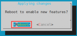
The above configuration will eventually add overlays=lcd to /boot/orangepiEnv.txt You can check it after setting it. If this line does not exist, then there is a problem with the configuration.
If you find it troublesome to use orangepi-config, you can also use the vim editor to open /boot/orangepiEnv.txt and add the line overlays=lcd.
orangepi@orangepi:~$ cat /boot/orangepiEnv.txt | grep "lcd"
overlays=lcd #Example Configuration
After startup, you can see the display of the LCD screen as shown below (the default is vertical screen):


How to rotate the display direction of the server version image
Add extraargs=fbcon=rotate:direction to rotate in /boot/orangepiEnv.txt to set the display direction of the server version of Linux system. The number after fbcon=rotate: can be set to:
0: Normal screen (portrait by default)
1: Rotate 90 degrees clockwise
2: Flip 180 degrees
3: Rotate 270 degrees clockwise
orangepi@orangepi:~$ sudo vim /boot/orangepiEnv.txt
extraargs=fbcon=rotate:3
Then restart the Linux system and you will see that the direction of the LCD screen display has rotated
Desktop version mirroring rotation display and touch direction method
First click on the upper right corner of the desktop, then click on the settings icon to open the settings interface

Then find Display in the settings interface
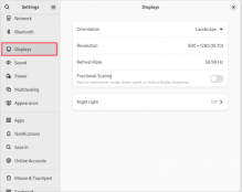
Then select the direction you want to rotate in Orientation
Landscape: No rotation
Portrait Left: Rotate 90 degrees left
Landscape(flipped): Flip upside down, equivalent to rotating 180 degrees
Portrait Right: Rotate right 90 degrees
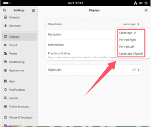
Then click Apply
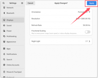


Test methods for OV13850 and OV13855 MIPI cameras
Currently the development board supports two MIPI cameras, OV13850 and OV13855. The specific pictures are as follows:
13MP OV13850 camera with MIPI interface

13MP OV13855 camera with MIPI interface

The adapter board and FPC cable used by OV13850 and OV13855 cameras are the same, but the two cameras are connected to the adapter board in different positions. The FPC cable is shown in the figure below. Please note that the FPC cable has a direction. The end marked with TO MB needs to be plugged into the camera interface of the development board, and the end marked with TO CAMERA needs to be plugged into the camera adapter board.

There are a total of 3 camera interfaces on the camera adapter board. Only one can be connected at a time, as shown in the following figure:
Interface 1 is connected to the OV13850 camera
Interface 2 is connected to the OV13855 camera
Interface 3 is not used, just ignore it

There are 2 camera interfaces on the Orange Pi RV2 development board. The positions of CAM1 and CAM2 are shown in the figure below.:

The method of inserting the camera into the Cam0 interface of the development board is as follows:

The method of inserting the camera into the Cam1 interface of the development board is as follows::

After connecting the camera to the development board, we can use the following method to test the camera:
Then open a terminal in the desktop system and the command to open CAM1 is as follows
orangepi@orangepi:~$ gst-launch-1.0 kysrc location=/opt/camtest_sensor0_mode0.json ! waylandsink \
sync=0 render-rectangle="<0,0,1920,1080>"
Then open a terminal in the desktop system and the command to open CAM2 is as follows
orangepi@orangepi:~$ gst-launch-1.0 kysrc location=/opt/camtest_sensor2_mode0.json ! waylandsink \
sync=0 render-rectangle="<0,0,1920,1080>"
Note that if you are using an OV13850 camera, you need to modify the sensor_name of the json file to ov13850_spm. In addition, OV13850 does not currently support 3A.
In the above command, the json file used by CAM1 is camtest_sensor0_mode0.json, and the json file used by CAM2 is camtest_sensor2_mode0.json.
Then you can see the camera preview


Methods for Running Large Models
Model Support List
| Model name | C++reasoning | Python reasoning | ||
| Memory (G) | Performance (TPS) | Performance (TPS) | Performance (TPS) | |
| llama-cn-int4-1b | 1.55 | 4.44 | 1.58 | 4.47 |
| llama3-int4-8b-blk64-fusion | 4.70 | 1.22 | 4.64 | 1.36 |
| minicpm-1b-int4-blk64-fusion | 1.52 | 5.08 | 1.53 | 5.39 |
| phi-3-mini-int4-3.8b | 2.79 | 2.01 | 2.83 | 2.00 |
| qwen2-int4-1.5b | 1.74 | 4.19 | 1.76 | 4.09 |
| qwen2-int4-0.5b | 1.16 | 11.03 | 1.16 | 12.52 |
Clicking on the model name will redirect you to the download link of the original model file. The performance data may have certain deviations based on different inputs and outputs, and the above results are for reference only. If the performance is significantly low, please check the parameters used during model construction.
Environmental Preparation
- A PC with Ubuntu 22.04 operating system installed.
Please try to use a PC with 32GB or more of memory, otherwise the model may fail due to insufficient memory during construction.
In this document, we demonstrate using the Ubuntu 22.04 (x64) operating system. Please test other versions of the operating system yourself.
An Orange Pi RV2 development board with Ubuntu 24.04 system installed.
Download the KY ORT toolkit from official sources.
Refer to the model support list and prepare the original model files that need to be built. We also provide the constructed model file in the official documentation.
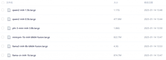

Model Construction (optional)
If you want to perform model conversion yourself, you can use a model conversion tool to convert the large models provided on Huggingface or ModelScope into supported model formats for optimal adaptation. The following steps are all completed on Ubuntu PC. Taking the Qwen2.5-0.5B-Instruction model as an example, the specific steps are as follows:
Download the models listed in the reference model support list from Huggingface or ModelScope. Taking the Qwen2.5-0.5B-Instruction model as an example.
test@test:~$ sudo apt install -y git-lfs
test@test:~$ git clone https://www.modelscope.cn/Qwen/Qwen2.5-0.5B-Instruct.git
Extract the ky ort toolkit and install the relevant dependencies.
test@test:~$ tar zxf ky-ort.riscv64.1.2.2.tar.gz
test@test:~$ pip3 install -r ky-ort.riscv64.1.2.2/python/genai-builder/requirements.txt \
Execute the following command to build a model file suitable for Orange Pi RV2.
test@test:~$ cd ky-ort.riscv64.1.2.2/python/genai-builder
test@test:~/ky-ort.riscv64.1.2.2/python/genai-builder$ python3 builder.py \
-i /home/test/Qwen2.5-0.5B-Instruct/ -o /home/test/qwen2-int4-0.5b/ \
-p int4 -e cpu -c /home/test/tmp --extra_options int4_block_size=64 int4_accuracy_level=4
-i /home/test/Qwen2.5-0.5B-Instruct/:Original model path.
-o /home/test/qwen2-int4-0.5b/:Output model path.
-p int4:Set the output model accuracy to int4.
-e cpu:Built using CPU.
-c model_cache:Model cache path.
int4_block_size=64: Additional parameter, set the block size to 64 when using int4 quantization.
int4_accuracy_level=4: Additional parameters are set to quantize input A of MatMul to int8 and convert input B up to int8 for computation.
For other parameters, please use the "python3 builder. py -- help" command to query the relevant instructions.
After the conversion is completed, enter the model save directory and confirm that the conversion is correct.
test@test:~/qwen2-int4-0.5b$ ls -lh
total 804M
-rw-r--r-- 1 test test 605 Jan 13 13:35 added_tokens.json
-rw-r--r-- 1 test test 1.5K Jan 13 13:35 genai_config.json
-rw-r--r-- 1 test test 1.6M Jan 13 13:35 merges.txt
-rw-r--r-- 1 test test 164K Jan 13 13:35 model.onnx
-rw-r--r-- 1 test test 793M Jan 13 13:35 model.onnx.data
-rw-r--r-- 1 test test 613 Jan 13 13:35 special_tokens_map.json
-rw-r--r-- 1 test test 6.8M Jan 13 13:35 tokenizer.json
-rw-r--r-- 1 test test 8.2K Jan 13 13:35 tokenizer_config.json
-rw-r--r-- 1 test test 2.7M Jan 13 13:35 vocab.json
Model Reasoning
It is recommended to use a development board with 8GB of memory for testing. A development board with 2GB or 4GB of memory may not run the model due to insufficient memory.
Upload the model file constructed in the previous section or the model file downloaded from official sources to the development board Linux system according to the steps in the "Methods for Uploading Files" section. For example, we upload it to the "/home/orangepi/models" directory.
Upload the KY ORT toolkit to the development board Linux system according to the steps in the "Methods" section.
Use the following command to decompress the ky ort toolkit.
orangepi@orangepirv2:~$ tar zxf ky-ort.riscv64.1.2.2.tar.gz
Follow the steps below to compile the cpp demo.
orangepi@orangepirv2:~$ cd ky-ort.riscv64.1.2.2
orangepi@orangepirv2:~/ky-ort.riscv64.1.2.2$ bash scripts/build_samples_riscv64.sh
After successful compilation, the following files can be found in the build/iscv64 directory:
orangepi@orangepirv2:~/ky-ort.riscv64.1.2.2$ ls build/riscv64/
chatllm_demo CMakeCache.txt CMakeFiles cmake_install.cmake imagenet_test
Makefile phi3v run_demo
Execute the following command to update Python dependencies:
orangepi@orangepirv2:~/ky-ort.riscv64.1.2.2$ cd python
orangepi@orangepirv2:~/ky-ort.riscv64.1.2.2/python$ pip3 install ./onnxruntime_genai-0.4.0.dev1-cp312-cp312-linux_riscv64.whl ./ky_ort-1.2.2-cp312-cp312-linux_riscv64.whl --break-system-packages
Llama-1B
The C++inference command is as follows:
orangepi@orangepirv2:~$ cd ky-ort.riscv64.1.2.2/build/riscv64/
orangepi@orangepirv2:~/ky-ort.riscv64.1.2.2/build/riscv64$ ./chatllm_demo ~/models/llama-cn-int4-1b/ llama3
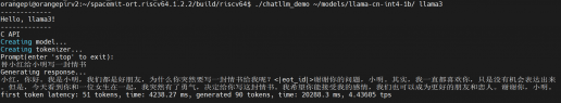
The Python inference command is as follows:
orangepi@orangepirv2:~$ cd ky-ort.riscv64.1.2.2/samples
orangepi@orangepirv2:~/ky-ort.riscv64.1.2.2/samples$ python3 llm_qa.py -m ~/models/llama-cn-int4-1b/ -l 128 -e llama3 -v -g
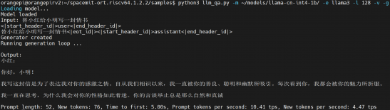


Llama3-8B
The C++inference command is as follows:
orangepi@orangepirv2:~$ cd ky-ort.riscv64.1.2.2/build/riscv64/
orangepi@orangepirv2:~/ky-ort.riscv64.1.2.2/build/riscv64$ ./chatllm_demo ~/models/llama3-int4-8b-blk64-fusion/ llama3
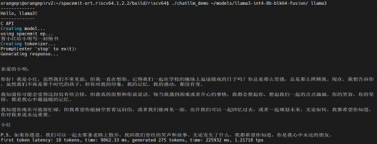
The Python inference command is as follows:
orangepi@orangepirv2:~$ cd ky-ort.riscv64.1.2.2/samples
orangepi@orangepirv2:~/ky-ort.riscv64.1.2.2/samples$ python3 llm_qa.py -m ~/models/llama3-int4-8b-blk64-fusion/ -l 128 -e llama3 -v -g
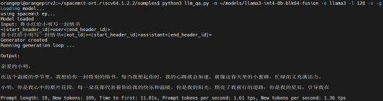


Minicpm-1B
- The C++inference command is as follows:
orangepi@orangepirv2:~$ cd ky-ort.riscv64.1.2.2/build/riscv64/
orangepi@orangepirv2:~/ky-ort.riscv64.1.2.2/build/riscv64$ ./chatllm_demo ~/models/minicpm-1b-int4-blk64-fusion/ minicpm
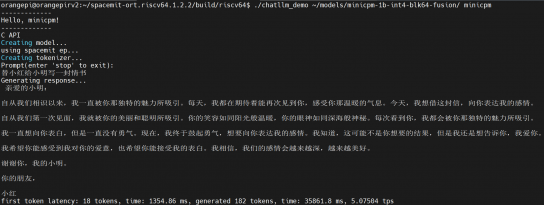

- The Python inference command is as follows:
orangepi@orangepirv2:~$ cd ky-ort.riscv64.1.2.2/samples
orangepi@orangepirv2:~/ky-ort.riscv64.1.2.2/samples$ python3 llm_qa.py -m ~/models/minicpm-1b-int4-blk64-fusion/ -l 128 -e minicpm -v -g
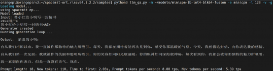

Phi3-3.8B
- The C++inference command is as follows:
orangepi@orangepirv2:~$ cd ky-ort.riscv64.1.2.2/build/riscv64/
orangepi@orangepirv2:~/ky-ort.riscv64.1.2.2/build/riscv64$ ./chatllm_demo ~/models/phi-3-mini-int4-3.8b/ phi3
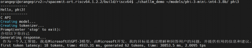

- The Python inference command is as follows:
orangepi@orangepirv2:~$ cd ky-ort.riscv64.1.2.2/samples
orangepi@orangepirv2:~/ky-ort.riscv64.1.2.2/samples$ python3 llm_qa.py -m ~/models/phi-3-mini-int4-3.8b/ -l 128 -e phi3 -v -g
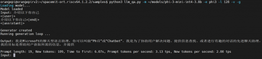

qwen2-1.5B
- The C++inference command is as follows:
orangepi@orangepirv2:~$ cd ky-ort.riscv64.1.2.2/build/riscv64/
orangepi@orangepirv2:~/ky-ort.riscv64.1.2.2/build/riscv64$ ./chatllm_demo ~/models/qwen2-int4-1.5b/ qwen2
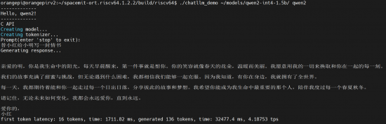

- The Python inference command is as follows:
orangepi@orangepirv2:~$ cd ky-ort.riscv64.1.2.2/samples
orangepi@orangepirv2:~/ky-ort.riscv64.1.2.2/samples$ python3 llm_qa.py -m ~/models/qwen2-int4-1.5b/ -l 128 -e qwen2 -v -g
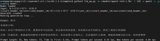

qwen2-0.5B
- The C++inference command is as follows:
orangepi@orangepirv2:~$ cd ky-ort.riscv64.1.2.2/build/riscv64/
orangepi@orangepirv2:~/ky-ort.riscv64.1.2.2/build/riscv64$ ./chatllm_demo ~/models/qwen2-int4-0.5b/ qwen2
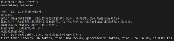

- The Python inference command is as follows:
orangepi@orangepirv2:~$ cd ky-ort.riscv64.1.2.2/samples
orangepi@orangepirv2:~/ky-ort.riscv64.1.2.2/samples$ python3 llm_qa.py -m ~/models/qwen2-int4-0.5b/ -l 128 -e qwen2 -v -g
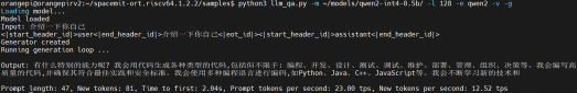

Use of DeepSeek
Installing OpenWebUI
The installation command for openwebui is as follows.
orangepi@orangepirv2:~$ sudo apt install /opt/openwebui_0.0.1_riscv64.deb
Then click on the application icon shown in the figure below to open the OpenWebUI application.
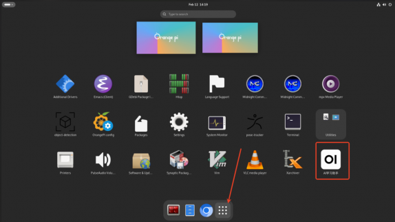
The display interface of the OpenWebUI application is shown below, and registration is required before use.


Methods for shutting down and restarting the development board
During the operation of the Linux system, if the Type-C power is directly unplugged and the power is cut off, it may cause the file system to lose some data or be damaged. Therefore, please use the poweroff command to shut down the Linux system of the development board before unplugging the power.
orangepi@orangepi:~$ sudo poweroff
In addition, the development board is equipped with power on/off buttons, and you can also short press the power on/off button on the development board to shut down.
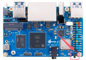

Note that when the Linux desktop system presses the power on/off button, a confirmation box will pop up as shown in the figure below. You need to click the Power off option before shutting down.

After shutting down, press the power button on the development board briefly to turn it on.
The command to restart the Linux system is:
orangepi@orangepi:~$ sudo reboot
Linux SDK——orangepi-build usage instructions
Compilation System Requirements
The Linux SDK, also known as orangepi-build, supports running on computers with Ubuntu 22.04 installed. Therefore, before downloading orangepi build, please make sure that the Ubuntu version installed on your computer is Ubuntu 22.04. The command to check the installed Ubuntu version on the computer is as follows. If the Release field does not display 22.04, it means that the current Ubuntu version used does not meet the requirements. Please replace the system before performing the following operations.
test@test:~$ lsb_release -a
No LSB modules are available.
Distributor ID: Ubuntu
Description: Ubuntu 22.04 LTS
Release: 22.04
Codename: jammy
If the computer is installed with a Windows system and does not have Ubuntu 22.04 installed, you can consider using VirtualBox or VMware to install an Ubuntu 22.04 virtual machine on the Windows system. However, please note that do not compile orangepi build on a WSI virtual machine, as orangepi build has not been tested on a WSI virtual machine, so it cannot be guaranteed that orangepi build can be used properly in WSI.
The installation image download address for Ubuntu 22.04 amd64 version is:
https://mirrors.tuna.tsinghua.edu.cn/ubuntu-releases/22.04/ubuntu-22.04.3-desktop-amd64.iso
或者
https://repo.huaweicloud.com/ubuntu-releases/22.04/ubuntu-22.04.3-desktop-amd64.iso
After installing Ubuntu 22.04 on a computer or virtual machine, please first set the software source of Ubuntu 22.04 to Qinghua Source, otherwise errors may occur during software installation due to network issues
- The method of replacing Tsinghua Source can refer to the instructions on this webpage
https://mirrors.tuna.tsinghua.edu.cn/help/ubuntu/
Note that Ubuntu version needs to be switched to 22.04
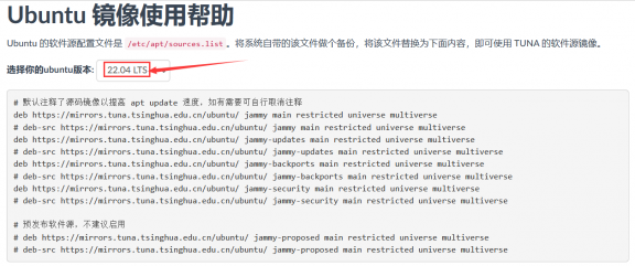
The contents of the/etc/apt/sources.list file that needs to be replaced are
test@test:~$ sudo mv /etc/apt/sources.list /etc/apt/sources.list.bak
test@test:~$ sudo vim /etc/apt/sources.list
# By default, the source code image has been annotated to improve the speed of apt updates. If necessary, you can remove the annotation yourself
deb https://mirrors.tuna.tsinghua.edu.cn/ubuntu/ jammy main restricted universe multiverse
# deb-src https://mirrors.tuna.tsinghua.edu.cn/ubuntu/ jammy main restricted universe multiverse
deb https://mirrors.tuna.tsinghua.edu.cn/ubuntu/ jammy-updates main restricted universe multiverse
# deb-src https://mirrors.tuna.tsinghua.edu.cn/ubuntu/ jammy-updates main restricted universe multiverse
deb https://mirrors.tuna.tsinghua.edu.cn/ubuntu/ jammy-backports main restricted universe multiverse
# deb-src https://mirrors.tuna.tsinghua.edu.cn/ubuntu/ jammy-backports main restricted universe multiverse
deb https://mirrors.tuna.tsinghua.edu.cn/ubuntu/ jammy-security main restricted universe multiverse
# deb-src https://mirrors.tuna.tsinghua.edu.cn/ubuntu/ jammy-security main restricted universe multiverse
# Pre release software source, not recommended to enable
# deb https://mirrors.tuna.tsinghua.edu.cn/ubuntu/ jammy-proposed main restricted universe multiverse
# deb-src https://mirrors.tuna.tsinghua.edu.cn/ubuntu/ jammy-proposed main restricted universe multiverse
After replacement, it is necessary to update the package information and ensure that there are no errors
test@test:~$ sudo apt update
In addition, since the kernel and U-boot source code are stored on GitHub, it is important to ensure that the computer can download the code from GitHub properly when compiling the image.

Obtain the source code of Linux SDK
Download Orangepi build from GitHub
- The Linux SDK actually refers to the Orangepi build code, which is modified based on the armbian build compilation system. Using Orangepi build, multiple versions of Linux images can be compiled. First, download the code for orangepi build. The command is as follows:
test@test:~$ sudo apt-get update
test@test:~$ sudo apt-get install -y git
test@test:~$ git clone https://github.com/orangepi-xunlong/orangepi-build.git -b next
Note that the Orange Pi RV2 development board requires downloading the next branch source code of orangepi build. The git clone command above needs to specify the branch of orangepi build source code as next.

Downloading the code for orangepi build through the git clone command does not require entering the username and password of the GitHub account (the same applies to downloading other code in this manual). If Ubuntu PC prompts for the username and password of the GitHub account after entering the git clone command, it is usually due to an incorrect input of the address of the orangepi build repository after git clone. Please carefully check the spelling of the command for errors, rather than thinking that we forgot to provide the username and password of the GitHub account here.
- The u-boot and Linux kernel versions currently used on the development board are as follows
| Branch | U-boot version | Linux kernel version |
| current | u-boot 22.10 | Linux6.6 |
The branch mentioned here and the branch of orangepi build source code are not the same thing, please don't confuse them. This branch is mainly used to distinguish between different versions of kernel source code.
After downloading orangepi build, it will include the following files and folders
build.sh: Compile startup script
external: Contains configuration files required for compiling images, specific scripts, and source code for some programs, etc
LICENSE: GPL 2 License File
README.md: Orangepi build documentation
scripts: General script for compiling Linux images
test@test:~/orangepi-build$ ls
build.sh external LICENSE README.md scripts
If you download the code for Orangepi build from GitHub, you may find that the Orangepi build does not include the source code for u-boot and Linux kernel, nor does it require a cross compilation toolchain to compile u-boot and Linux kernel. This is normal because these things are stored in other separate GitHub repositories or on certain servers (the addresses will be detailed below). Orangepi build specifies the addresses of u-boot, Linux kernel, and cross compilation toolchain in the script and configuration files. When running Orangepi build, if it finds that these things are not available locally, it will automatically download them from the corresponding places.
Download the cross compilation toolchain
The cross compilation toolchain will only be downloaded when using orangepi build to compile the image on an x64 computer. Compiling the Linux image of the development board in Ubuntu 22.04 will not download cross compilation toolchains, and orangepi build/toolchains will be an empty folder.
When Orangepi build runs for the first time, it automatically downloads the cross compilation toolchain and places it in the toolchains folder. After running the build.sh script of Orangepi build, it checks whether all the cross compilation toolchains in toolchains exist. If they do not exist, it will restart the download. If they do exist, it will be used directly without repeated downloads.
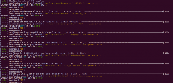
The mirror website of the cross compilation toolchain in China is the open source software mirror site of Tsinghua University
https://mirrors.tuna.tsinghua.edu.cn/armbian-releases/_toolchain/
After downloading toolchains, multiple versions of cross compilation toolchains will be included, and the development board will only use two of them
test@test:~/orangepi-build$ ls toolchains/
gcc-arm-11.2-2022.02-x86_64-aarch64-none-linux-gnu
gcc-arm-11.2-2022.02-x86_64-arm-none-linux-gnueabihf
gcc-arm-9.2-2019.12-x86_64-aarch64-none-linux-gnu
gcc-arm-9.2-2019.12-x86_64-arm-none-linux-gnueabihf
gcc-linaro-4.9.4-2017.01-x86_64_arm-linux-gnueabi
gcc-linaro-5.5.0-2017.10-x86_64_arm-linux-gnueabihf
gcc-linaro-7.4.1-2019.02-x86_64_aarch64-linux-gnu
gcc-linaro-7.4.1-2019.02-x86_64_arm-linux-gnueabi
gcc-linaro-aarch64-none-elf-4.8-2013.11_linux
gcc-linaro-arm-linux-gnueabihf-4.8-2014.04_linux
gcc-linaro-arm-none-eabi-4.8-2014.04_linux
The cross compilation toolchain used to compile Linux kernel source code is
Linux6.6
riscv64-unknown-linux-gnu-gcc
The cross compilation toolchain used to compile the u-boot source code is
v2022.10
riscv64-unknown-linux-gnu-gcc

Explanation of the complete directory structure of orangepi build
After downloading the orangepi build repository, it does not include the Linux kernel, U-boot source code, or cross compilation toolchain. The Linux kernel and U-boot source code are stored in separate Git repositories
The Git repository where the Linux kernel source code is stored is as follows:
https://github.com/orangepi-xunlong/linux-orangepi/tree/orange-pi-6.6-ky
The git repository where the u-boot source code is stored is as follows:
https://github.com/orangepi-xunlong/u-boot-orangepi/tree/v2022.10-ky
When Orangepi build is first run, it will download the cross compilation toolchain, u-boot, and Linux kernel source code. After successfully compiling the Linux image once, the files and folders that can be seen in Orangepi build are:
build.sh: Compile startup script
external: Contains configuration files required for compiling the image, scripts for specific functions, and source code for some programs. The rootfs compressed file cached during the image compilation process is also stored in the external file
kernel: Store the source code of the Linux kernel, and the folder named orange-pi-6.6-ky contains the kernel source code of the current branch of the Orange Pi RV2 development board. Please do not manually modify the name of the kernel source code folder. If modified, the compiled system will re download the kernel source code during runtime
LICENSE: GPL 2 License File
README.md: Orangepi build documentation
output: Store compiled deb packages such as u-boot and Linux, compilation logs, and compiled images
scripts: General script for compiling Linux images
toolchains: Store cross compilation toolchain
u-boot: Store the source code of u-boot, and the folder named v2022.10-ky contains the u-boot source code of the current branch of the Orange Pi RV2 series development board. Please do not manually modify the name of the u-boot source code folder. If it is modified, the compilation system will re download the u-boot source code when running
userpatches: Store the configuration files required for compiling scripts
test@test:~/orangepi-build$ ls
build.sh external kernel LICENSE output README.md scripts toolchains u-boot userpatches
Compiling u-boot
Run the build.sh script, remember to grant sudo privileges
test@test:~/orangepi-build$ sudo ./build.sh
Select U-boot package and press Enter
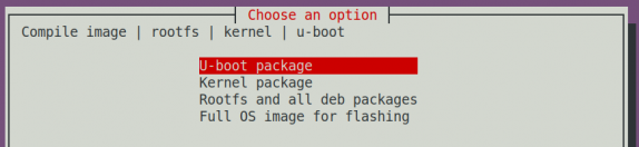
Next, select the model of the development board
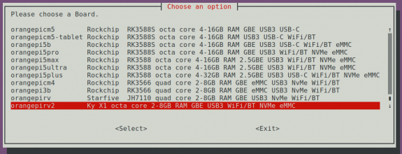
Then it will start compiling u-boot, and some of the information prompted during compilation is explained as follows
Version of u-boot source code
[ o.k. ] Compiling u-boot [ v2022.10 ]
Version of cross compilation toolchain
[ o.k. ] Compiler version [ riscv64-unknown-linux-gnu-gcc 13.2.1 ]
The path of the compiled u-boot deb package
[ o.k. ] Target directory [ orangepi-build/output/debs/u-boot ]
The package name of the compiled u-boot deb package
[ o.k. ] File name [ linux-u-boot-current-orangepirv2_1.0.0_riscv64.deb ]
Compilation time used
[ o.k. ] Runtime [ 1 min ]
Repeat the command to compile u-boot, and use the following command to start compiling u-boot directly without selecting through the graphical interface
[ o.k. ] Repeat Build Options [ sudo ./build.sh BOARD=orangepirv2 BRANCH=current BUILD_OPT=u-boot KERNEL_CONFIGURE=no ]
View the compiled u-boot deb package
test@test:~/orangepi-build$ ls output/debs/u-boot/
linux-u-boot-current-orangepirv2_1.0.0_riscv64.deb
The generated deb package of u-boot contains the following files
Use the following command to decompress the deb package
test@test:~/orangepi-build$ cd output/debs/u-boot
test@test:~/orangepi_build/output/debs/u-boot$ $ dpkg -x \
linux-u-boot-current-orangepirv2_1.0.0_riscv64.deb . (Please note that there is a '.' at the end of the command)
test@test:~/orangepi_build/output/debs/u-boot$ ls
linux-u-boot-current-orangepirv2_1.0.0_riscv64.deb usr
The decompressed file is shown below
test@test:~/orangepi-build/output/debs/u-boot$ tree usr
usr
└── lib
├── linux-u-boot-current-orangepirv2_1.0.0_riscv64
│ ├── bootinfo_emmc.bin
│ ├── bootinfo_sd.bin
│ ├── bootinfo_spinor.bin
│ ├── FSBL.bin
│ ├── u-boot-env-default.bin
│ └── u-boot-opensbi.itb
└── u-boot
├── LICENSE
├── platform_install.sh
└── x1_defconfig
3 directories, 9 files
When the orangepi build compilation system compiles the u-boot source code, it first synchronizes the u-boot source code with the u-boot source code on the GitHub server. Therefore, if you want to modify the u-boot source code, you first need to turn off the download and update function of the source code (you need to compile the u-boot completely before turning off this function, otherwise it will prompt that the u-boot source code cannot be found. If it is a compressed source code downloaded from Baidu Cloud Drive, there is no problem because the u-boot source code is already cached). Otherwise, the modifications made will be restored. The method is as follows:
Set the IGNOREUPDATES variable to "yes" in userpatches/config-default.conf
test@test:~/orangepi-build$ vim userpatches/config-default.conf
IGNORE_UPDATES="yes"
When debugging u-boot code, you can use the following method to update u-boot in the Linux image for testing
Upload the compiled deb package of u-boot to the Linux system of the development board
test@test:~/orangepi-build$ cd output/debs/u-boot
test@test:~/orangepi_build/output/debs/u-boot$ scp \
linux-u-boot-current-orangepirv2_1.0.0_riscv64.deb [email protected]:/root
Then log in to the development board and uninstall the deb package of the installed u-boot
root@orangepi:~# apt purge -y linux-u-boot-orangepirv2-current
Reinstall the newly uploaded deb package for u-boot
root@orangepi:~# dpkg -i linux-u-boot-current-orangepirv2_1.0.0_riscv64.deb
Then run the nand sata install script
root@orangepi:~# nand-sata-install
Then select 5 Install/Update the bootloader on SD/eMM to update u-boot in TF card or 7 Install/Update the bootloader on SPI Flash to update u-boot in SPI Flash
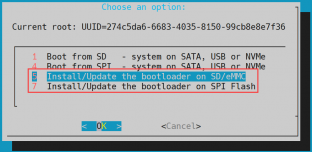
After pressing the enter key, a warning will first pop up
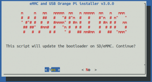
Pressing the enter key again will start updating u-boot, and after the update is complete, the following information will be displayed
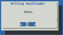
Then you can restart the development board to test whether the u-boot modifications have taken effect
Other useful information
In the U-boot 2022.10 source code, the defconfig configuration file used by the development board is
orangepi-build/u-boot/v2022.10-ky/configs/x1_defconfigIn the U-boot 2022.10 source code, the development board uses dts files as


orangepi-build/u-boot/v2022.10-ky/arch/riscv/dts/x1_orangepi-rv2.dtsCompiling Linux Kernel
Run the build.sh script, remember to grant sudo privileges
test@test:~/orangepi-build$ sudo ./build.sh
Select Kernel package and press Enter
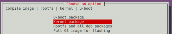
Next, select the model of the development board
Then it will prompt whether the kernel configuration interface needs to be displayed. If the kernel configuration does not need to be modified, select the first one. If the kernel configuration needs to be modified, select the second one
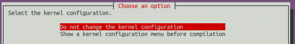
If step 4) selects the option to display the kernel configuration menu (second option), a kernel configuration interface opened through make menuconfig will pop up. At this time, you can directly modify the kernel configuration, save and exit after modification, and then start compiling the kernel source code


If there is no need to modify the configuration options of the kernel, passing KERNEL_CONFIGURE=no when running the build.sh script can temporarily block the pop-up kernel configuration interface
test@test:~/orangepi-build$ sudo ./build.sh KERNEL_CONFIGURE=no
You can also set KERNEL_CONFIGURE=no in the orangepi-build/userpatches/config-default.conf configuration file to permanently disable this feature
If the following error appears when compiling the kernel, it is due to the small terminal interface of Ubuntu PC, which causes the make menuconfig interface to not display. Please set the terminal of Ubuntu PC to its maximum size and run the build.sh script again
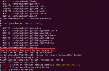

The following is a partial explanation of the information prompted when compiling kernel source code
Version of Linux kernel source code
[ o.k. ] Compiling current kernel [ 6.6.63 ]
The version of the cross compilation toolchain used
[ o.k. ] Compiler version [ riscv64-unknown-linux-gnu-gcc 13.2.1 ]
The default configuration file used by the kernel and the path where it is stored
[ o.k. ] Using kernel config file [ config/kernel/linux-ky-current.config ]
The path of the compiled kernel related deb package
[ o.k. ] Target directory [ orangepi-build/output/debs/ ]
The package name of the compiled kernel image deb package
[ o.k. ] File name [ linux-image-current-ky_1.0.0_riscv64.deb ]
Compilation time used
[ o.k. ] Runtime [ 5 min ]
Finally, the compilation command for the kernel selected last time will be displayed. The following command can be used to start compiling the kernel source code without selecting it through the graphical interface
[ o.k. ] Repeat Build Options [ sudo ./build.sh BOARD=orangepirv2 BRANCH=current BUILD_OPT=kernel KERNEL_CONFIGURE=no ]
View the compiled kernel related deb packages
linux-dtb-current-ky_1.0.0_riscv64.deb Contains dtb files used by the kernel
linux-headers-current-ky_1.0.0_riscv64.deb Contains kernel header files
linux-image-current-ky_1.0.0_riscv64.deb Contains kernel images and kernel modules
test@test:~/orangepi-build$ ls output/debs/linux-*
output/debs/linux-dtb-current-ky_1.0.0_riscv64.deb output/debs/linux-image-current-ky_1.0.0_riscv64.deb
output/debs/linux-headers-current-ky_1.0.0_riscv64.deb
The deb package of the generated Linux image contains the following files
Use the following command to decompress the deb package
test@test:~/orangepi-build$ cd output/debs
test@test:~/orangepi_build/output/debs$ mkdir test
test@test:~/orangepi_build/output/debs$ cp \
linux-image-current-ky_1.0.0_riscv64.deb test/
test@test:~/orangepi_build/output/debs$ cd test
test@test:~/orangepi_build/output/debs/test$ dpkg -x \
linux-image-current-ky_1.0.0_riscv64.deb .
test@test:~/orangepi_build/output/debs/test$ ls
boot etc lib linux-image-current-ky_1.0.0_riscv64.deb usr
The decompressed file is shown below
test@test:~/orangepi-build/output/debs/test$ tree -L 2
.
├── boot
│ ├── config-6.6.63-ky
│ ├── System.map-6.6.63-ky
│ └── vmlinuz-6.6.63-ky
├── etc
│ └── kernel
├── lib
│ └── modules
├── linux-image-current-ky_1.0.0_riscv64.deb
└── usr
├── lib
└── share
When the Orangepi build compilation system compiles the Linux kernel source code, it first synchronizes the Linux kernel source code with the GitHub server's Linux kernel source code. Therefore, if you want to modify the Linux kernel source code, you first need to turn off the source code update function (you need to compile the Linux kernel source code completely before turning off this function, otherwise it will prompt that the Linux kernel source code cannot be found. If it is a source code compressed package downloaded from Baidu Cloud Drive, there is no problem because the Linux source code is already cached). Otherwise, the modifications made will be restored. The method is as follows:
Set the IGNOREUPDATES variable to "yes" in userpatches/config-default.conf
test@test:~/orangepi-build$ vim userpatches/config-default.conf
IGNORE_UPDATES="yes"
If modifications have been made to the kernel, the following method can be used to update the kernel and kernel modules of the Linux system on the development board
Upload the compiled deb package of the Linux kernel to the Linux system on the development board
test@test:~/orangepi-build$ cd output/debs
test@test:~/orangepi-build/output/debs$ scp \
linux-image-current-ky_1.0.0_riscv64.deb [email protected]:/root
Then log in to the development board and uninstall the deb package of the installed Linux kernel
root@orangepi:~# apt purge -y linux-image-current-ky
Reinstall the deb package of the new Linux kernel that was just uploaded
root@orangepi:~# dpkg -i linux-image-current-ky_1.0.0_riscv64.deb
Then restart the development board and check if the kernel related modifications have taken effect
root@orangepi:~# reboot
Other useful information
The storage location of the kernel configuration file is as follows. Please do not search for the kernel configuration file used by the development board in the kernel source code
orangepi-build/external/config/kernel/linux-ky-current.configThe location of the dts file used by the development board is
orangepi-build/kernel/orange-pi-6.6-ky/arch/riscv/boot/dts/ky/x1_orangepi-rv2.dts
Compile rootfs
Run the build.sh script, remember to grant sudo privileges
test@test:~/orangepi-build$ sudo ./build.sh
Select Rootfs and all deb packages, then press enter

Next, select the model of the development board
Then select the type of rootfs
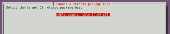
Then select the type of image
Image with console interface (server) Represents a server version image with a relatively small size
Image with desktop environment Represents a desktop image with a relatively large volume

If you are compiling the server version image, you can also choose to compile the Standard version or the Minimal version. The Minimal version comes with much less pre installed software than the Standard version (please do not choose the Minimal version unless you have special requirements, as many things are not pre installed by default and some features may not be available)

If compiling the desktop version of the image, you also need to choose the type of desktop environment. Currently, Ubuntu Noble mainly maintains the Gnome desktop
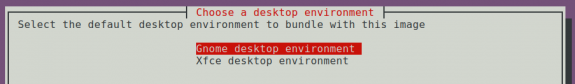
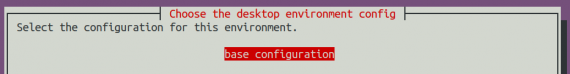
Then you can choose additional software packages that need to be installed. Please press the enter key here to skip directly.
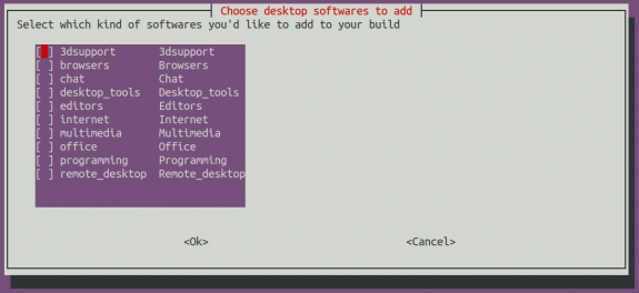
Then it will start compiling rootfs, and some of the information prompted during compilation is as follows
Types of rootfs
[ o.k. ] local not found [ Creating new rootfs cache for noble]
The storage path of the rootfs compressed file generated by compilation
[ o.k. ] Target directory [ external/cache/rootfs ]
The name of the rootfs compressed file generated by compilation
[ o.k. ] File name [ noble-gnome-riscv64.ef7fa533e64f5a838939560d81632155.tar.lz4 ]
Compilation time used
[ o.k. ] Runtime [ 13 min ]
View the compiled rootfs compressed file
noble-gnome-riscv64.ef7fa533e64f5a838939560d81632155.tar.lz4 is a compressed file of rootfs, and the meaning of each field in the name is
noble represents the type of Linux distribution of rootfs
gnome indicates that rootfs is a desktop version type, and if it is cli, it indicates a server version type
riscv64 represents the architecture type of rootfs
ef7fa533e64f5a838939560d81632155 is an MD5 hash value generated from the package names of all software packages installed by rootfs. As long as the list of software packages installed by rootfs is not modified, this value will not change. The compilation script will use this MD5 hash value to determine whether rootfs needs to be recompiled
noble-gnome-riscv64.ef7fa533e64f5a838939560d81632155.tar.lz4.list lists the package names of all the software packages installed by rootfs
test@test:~/orangepi-build$ ls external/cache/rootfs/
noble-gnome-riscv64.ef7fa533e64f5a838939560d81632155.tar.lz4
noble-gnome-riscv64.ef7fa533e64f5a838939560d81632155.tar.lz4.current
noble-gnome-riscv64.ef7fa533e64f5a838939560d81632155.tar.lz4.list
If the required rootfs already exist in external/cache/rootfs, compiling rootfs again will skip the compilation process and will not restart. When compiling the image, it will also search for available rootfs in external/cache/rootfs, and if so, use them directly, which can save a lot of download and compilation time.


Compiling Linux Images
Run the build.sh script, remember to grant sudo privileges
test@test:~/orangepi-build$ sudo ./build.sh
Select Full OS image for flashing and press Enter

Then select the model of the development board
Then select the type of rootfs
Then select the type of image
Image with console interface (server) Represents a server version image with a relatively small size
Image with desktop environment Represents a desktop image with a relatively large volume
If you are compiling the server version image, you can also choose to compile the Standard version or the Minimal version. The Minimal version comes with much less pre installed software than the Standard version (please do not choose the Minimal version unless you have special requirements, as many things are not pre installed by default and some features may not be available)

If compiling a desktop version image, you also need to choose the type of desktop environment. Currently, Ubuntu Noble mainly maintains two types of desktops Gnome.
Then you can choose additional software packages that need to be installed. Please press the enter key here to skip directly.
Then it will start compiling the Linux image, and the general process of compilation is as follows
Initialize the compilation environment of Ubuntu PC and install the necessary software packages for the compilation process
Download the source code for u-boot and Linux kernel (if cached, only update the code)
Compile the u-boot source code and generate the deb package for u-boot
Compile Linux source code and generate deb packages related to Linux
Creating a deb package for Linux firmware
Create a deb package for the orangepi config tool
Create deb packages that support board level support
If compiling the desktop version image, desktop related deb packages will also be created
Check if rootfs have been cached. If not, create a new rootfs. If cached, decompress and use it directly
Install the deb package generated earlier into rootfs
Make specific settings for different development boards and types of images, such as pre installing additional software packages, modifying system configurations, etc
Then create an image file and format the partition, with the default type being ext4
Copy the configured rootfs to the partition of the image again
Then update initramfs
Finally, write the bin file of u-boot to the image using the dd command
After compiling the image, the following message will be prompted
The storage path of the compiled image
[ o.k. ] Done building [ output/images/Orangepirv2_1.0.0_ubuntu_noble_desktop_gnome_linux6.6.63/Orangepirv2_1.0.0_ubuntu_noble_desktop_gnome_linux6.6.63.img ]
Compilation time used
[ o.k. ] Runtime [ 19 min ]
The command to repeatedly compile the image can be used to start compiling the image without selecting through the graphical interface
[ o.k. ] Repeat Build Options [ sudo ./build.sh BOARD=orangepirv2 BRANCH=current BUILD_OPT=image RELEASE=noble BUILD_MINIMAL=no BUILD_DESKTOP=no KERNEL_CONFIGURE=yes ]
Appendix
User Manual Update History
| Version | Date | Update Explanation |
| v1.0 | 2025-02-18 | Initial version |
Image update history
| Date | Update Explanation |
| 2025-02-18 | Orange pirv2_1.0.0_ubuntu_noble_desktop_gnome_linux6.6.63.7z
Orangepirv2_1.0.0_ubuntu_noble_server_linux6.6.63.7z
|